• Scam Alert. Members are reminded to NOT send money to buy anything. Don't buy things remote and have it shipped - go get it yourself, pay in person, and take your equipment with you. Scammers have burned people on this forum. Urgency, secrecy, excuses, selling for friend, newish members, FUD, are RED FLAGS. A video conference call is not adequate assurance. Face to face interactions are required. Please report suspicions to the forum admins. Stay Safe - anyone can get scammed.

Strange Carbide Insert Internal Threading Tool Geometry

your "it fits but doesn't" was a recurring issue for me as well.
A few points to consider:

1. An A60 insert is not intended for coarse pitches., most listings are wildy optimitic about their range. Too wide for fine pitches, too narrow for coarse pitches. On my A60's the tip width is typically .008" where a 13 tpi thread wants .0094" at the root (.125*pitch). You can fake this with compund parallel to the Z axis and offsetting slightly on a finish pass.
2. External thread depth is typically .6134* pitch, internal .5413*pitch, but it still requires proper tip width. A60 might not be able to go deep enough at coarse pitches without topping the threads.
3. Carbide bits don't like running in reverse, did you chip yours by running the spindle in reverse to back it out without winding the cutter clear?
4. Measuring your external thread with wires should confirm the above.

This is one time that the Machinery's Handbook is worth looking at, the thread proportions are fairly simple once you digest them.
For your desired pitch AG60 is a better bet, but again the tip width matters.

I generally end up putting the insert on my optical comparator, measure tip width and pass it by the d-bit grinder for correction depending on the thread I need.

Gerrit
Advancing the compound in the z-direction as you describe is how I've been doing it for 20 years when using non-topping (partial profile) inserts. I've had to start using topping (full profile) inserts now that I have a solid tool post.

NB I think your math is off regarding the root diameter for the 13 pitch, I believe it should be 0.019". Which is all the more reason to be able to have the ability to widen the root diameter of the thread, either with the compound, or full profile inserts.
 
1670243043963.webp
 

Yup, this is what I tried to explain earlier. A picture is worth a thousand words.

Three things to note in particular. 1. Your reference clearly shows that the high tilt is intentional. 2. The low clearance at the bottom of the insert caused by the material moving toward the tool as it rotates. 3. And the tilt of the tool required to provide that clearance.

Not sure why the tool is that far low though. Maybe exaggerated on purpose? I've always thought it should be higher, not lower. On the other hand, perhaps one should not look at the tool or the part in the context of a horizontal level. Nothing sacred about that. If the tool tilt is measured and applied relative to a different frame of reference that is tilted down vs the lathe bed then so be it. It could be vertical for all that matters. In fact, I regularly part upside down intentionally. It does result in less rigidity though. Not sure that matters that much with threading. The cosine affect of 15 degrees is basically still squatt.
 
Last edited:
NB I think your math is off regarding the root diameter for the 13 pitch, I believe it should be 0.019". Which is all the more reason to be able to have the ability to widen the root diameter of the thread, either with the compound, or full profile inserts.
You're right, the *.125 i for the external tip width. Serves me right for relying on memory :-)

Root width for external/tip for internal is .250*pitch.
 
Yup, this is what I tried to explain earlier. A picture is worth a thousand words.

Three things to note in particular. 1. Your reference clearly shows that the high tilt is intentional. 2. The low clearance at the bottom of the insert caused by the material moving toward the tool as it rotates. 3. And the tilt of the tool required to provide that clearance.

Not sure why the tool is that far low though. Maybe exaggerated on purpose? I've always thought it should be higher, not lower. On the other hand, perhaps one should not look at the tool or the part in the context of a horizontal level. Nothing sacred about that. If the tool tilt is measured and applied relative to a different frame of reference that is tilted down vs the lathe bed then so be it. It could be vertical for all that matters. In fact, I regularly part upside down intentionally. It does result in less rigidity though. Not sure that matters that much with threading. The cosine affect of 15 degrees is basically still squatt.
Yeah, the depictions appears low, but they have drawn the center line for reference, and the 10° & 15° angles are from that center line.
 
Yeah, the depictions appears low, but they have drawn the center line for reference, and the 10° & 15° angles are from that center line.

Ya, but the centerline they drew is not horizontal. It's already on a significant angle. Or at least that's how it looks. Hence my verbose discussion above. Just not real clear to me what the intent was there.
 
Ya, but the centerline they drew is not horizontal. It's already on a significant angle. Or at least that's how it looks. Hence my verbose discussion above. Just not real clear to me what the intent was there.
Yes, but you just stated that in your previous post, that the axis planes do not have to coincide with what we know as level. A lot of CNC lathes and turning centers, slant bed lathes are not "level" as we are use to, in the x-plane. As long as the tip of the cutter moves towards the dead center tangentially, then it doesn't matter. The cutter can be coming in from above, or below, the work piece, it wouldn't matter.
 
Yes, but you just stated that in your previous post, that the axis planes do not have to coincide with what we know as level. A lot of CNC lathes and turning centers, slant bed lathes are not "level" as we are use to, in the x-plane. As long as the tip of the cutter moves towards the dead center tangentially, then it doesn't matter. The cutter can be coming in from above, or below, the work piece, it wouldn't matter.

OK, so I take that to mean that you agree that the axis of application is tilted. And yes, I agree that this is of no major consequence for threading.

However, I think that this has two significant downsides though.

1. It's gunna be very confusing for users who cannot think or visualize the horizon on a relative angle. Just remember how much trouble it is to explain lathe axial alignment to most folks..... Or mill nod tramming...... LOL!

2. It will be very difficult to set proper tool height even for those who can easily think on a relative angle. Go ahead, give it a try! I'm laughing already! Ya, very painful!

Edit - do the insert folks even specify this angle?
Yes, its confusing! Absolutely! You do have to have spatial awareness, which often I don't have, to be able to visualize it. All the catalogues for machine tools and inserts are geared toward CNC production. We can still use almost everything they provide for our manual machines, but we have to change parameters to suit our needs and requirements.

The insert makers can't specify that angle, they don't know, or care what machine you have. The owners manual for your turning center will tell you how to find center of axis.

Why would it be difficult to find center? Have we not all done a facing cut and determined if we need to adjust our height by measuring or feeling the pip?

Sorry, again I wasn't very clear.

That's prolly why I'm already laughing! If you and I can't have a common understanding, what hope is there for anyone else!

I'll try to explain what I tried to say before a bit better: For the insert geometry you posted, the plane of center is on an angle. Therefore, the design tool working center height varies with distance toward or away from the axis of the spindle. It isn't a number in a book or manual. Although it might well be a formula, it's probably more a trial and error effort. For facing and your pip, it will always be the axis of the spindle no matter what angle the plane of center height is on. But for boring or threading as indicated in your photo, the plane, and therefore the design operating height setting, varies up or down as the design cutting point moves toward or away from the operator - in this case according to the size of the ID.

SO...... It looks to me like you are ducking the assignment by asking me to explain it instead of doing it yourself! Very clever Sir! But you will note that I didn't actually explain how to do it, just why it has to be done. So the ball is still in your court!

Ya, I'm laughing even more now!
 
Last edited:
For the insert geometry you posted, the plane of center is on an angle. Therefore, the design tool working center height varies with distance toward or away from the axis of the spindle.
But the tip height doesn't vary because the tool is moving parallel to what you called the plane of center.
Not sure why the tool is that far low though.
This I don't understand. I see the tip of that cutter dead on the center line which is shown by the dashed line.
 
Any straight line through the center of rotation (of the part in this case) will do to measure the relative insert angle as the resulting clearance will always be the same with the cutting tip on said straight line where it contacts the wall of the bore.

Orientation of the reference line has nothing to do with it.

I believe it has been pointed out above that many modern lathes do not have the classic “horizontal” bed and what’s more, the tools do not move on the classic “horizontal plane” of the classic cross slide / compound slide.

It’s all just relative angles…
 
Last edited:
@thestelster & @RobinHood .

Firstly, sorry for the delay. I am currently undergoing vision evaluation at a ophthalmologist. Ironically, I am dealing with said vision problems while I discuss vision issues in terms of drawings with you guys.

So, the problem is that the drawing provided by @thestelster is not a perfect isometric projection. We know this because the hole opening is perfectly round not vertically elliptical and yet there is an effort to convey perspective through a scale change with more distant objects. With this kind of projection a centerline should look like the red lines I have drawn on the original drawing. Not the very significantly sloped line the drawing has.

1670243043963~2.png


If I try really hard, I can see some variation in the wall thickness but nowhere near enough to reflect a projected centerline plane as shown. Perhaps at most, the very slight tilt I have drawn above. Using a reasonable modified point projection approach, I concluded that the dashed line is sloped down at the left and up at the right from a true horizontal alignment. Hence my comments about the difficulty of following that sloped plane when setting the tip height.

If I accept what you suggest and the sloped line is actually meant to be horizontal, then I agree with both of your points on this matter and the whole subject becomes trivial.

On the other hand, if I interpret the drawing as a modified point projection the way that it is actually drawn, it is very complex.

Since I don't use any inserts that are canted that aggressively, I have no experience to bias my views or my interpretation one way or the other. All I can go by is what I see in @YYCHM's original photo and the drawings that @thestelster provided. In so doing, I have probably created a fictitious situation requiring a non-linear centering alignment that would be extremely difficult to describe. Hence my challenge to @thestelster, which I would still like to hear just for Poops and Giggles!

I do have to point out that this would have been a lot easier for me to understand if we had not engaged in a discussion of the need to position the insert higher or lower than center for optimum performance. It would also have been better if the artist had followed standard practice for orthographic projections instead of creating something that is a mixed bag of non-standard approaches.

Since both of you believe that the sloped dotted line is actually meant to be horizontal, and both have significant experience using threading inserts, I'll simply accept your version of what was intended and move on.

Sorry for the confusion.
 
I have nothing to offer from the perspective of knowledge. But since I'm sitting around today not doing much I thought I'd sketch up what I have on hand. It's not for threading but it's the one I photographed that has the 10 degree slope. The axis of the part is on the centerline. The angled tool tip also on the centerline.
The clearance is there for the bottom of the carbide insert.
HeadstockView.jpg

Here's a view from the top.
TopView.webp

I believe the conversation above was that the boring bars for threading are inclined 15 degrees giving the tool bits perhaps even more clearance.
 
Last edited:
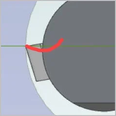
Yup, but inserts can also have a profile like red line (greatly exaggerated) which translates into a different rake angle than the nominal mounting plane of the insert itself. In this case it goes from negative like your sketch to positive or neutral or something in between. It might be called axial rake vs cutting rake, but don't hold me to that. I've seen different nomenclature for mill inserts than vs lathe inserts.
 

Attachments

  • EDT-2022-12-05 5.31.24 PM.webp
    EDT-2022-12-05 5.31.24 PM.webp
    2.6 KB · Views: 0
Yup, but inserts can also have a profile like red line (greatly exaggerated) which translates into a different rake angle than the nominal mounting plane of the insert itself. In this case it goes from negative like your sketch to positive or neutral or something in between. It might be called axial rake vs cutting rake, but don't hold me to that. I've seen different nomenclature for mill inserts than vs lathe inserts.
True. All I did was go online and find STEP file for a CCMT insert. Unlike my physical insert this one didn't have the rake you describe. My insert does create a positive rake although compared to HSS tooling it's still dull as a post. But then it was one of the 10 that came with t3 boring bars. I have some others that are specifically raked for aluminum that appear to have a steeper rake.

What I was trying to do with the drawings is to show that the angled slope of the insert base on the boring bar creates clearance at the bottom of the insert. That the movement of the tool bit at the center line follows the center line as the cross slide is moved.

But as I said. I know nothing. Just thought it was interesting.
 
Back
Top