• Scam Alert. Members are reminded to NOT send money to buy anything. Don't buy things remote and have it shipped - go get it yourself, pay in person, and take your equipment with you. Scammers have burned people on this forum. Urgency, secrecy, excuses, selling for friend, newish members, FUD, are RED FLAGS. A video conference call is not adequate assurance. Face to face interactions are required. Please report suspicions to the forum admins. Stay Safe - anyone can get scammed.

Standard Modern 11" Utilathe Dro?

I have the CX701 by Busybee.
I currently have two out of four (five? Bear with me...) axes done: my carriage (Z) and cross-slide (X).
I have an encoder on the spindle that drives my electronic gearing. I want to pull that signal back to the DRO as well so I can use it to set the spindle position. I might get to that this morning - I have a couple of hours to spend in the shop.
The fourth axis I'm considering is on the tailstock, which will be easy enough, I just haven't gotten there. I guess I don't do enough blind drilling.
The fifth axis would be the rotation of the compound. I keep noodling at ways to get a precise measure there and short of essentially mounting a rotary table to hold the compound I'm not finding great ways to proceed at the precision levels that would make it useful.
Have the same lathe, do you mind sharing pictures of the 2 already installed DRO's and a bit of info on the model chosen , thanks!
 
Have the same lathe, do you mind sharing pictures of the 2 already installed DRO's and a bit of info on the model chosen , thanks!
The X axis is here: https://canadianhobbymetalworkers.com/threads/whats-paul-up-to.6143/post-173636
The Z axis is here: https://canadianhobbymetalworkers.com/threads/whats-paul-up-to.6143/post-118320, though I didn't write much about it you can make out the little bracket dropping to reach under the ways. You can also see my older X axis setup, now replaced because it was awful (the stainless cover peeled away, probably from oil and swarf penetration).
With a picture of the tape:
1733005547289.png
And I discuss my ELS around https://canadianhobbymetalworkers.com/threads/whats-paul-up-to.6143/post-95279

I like my cx701. I was completely new to machining, and it is a completely usable first lathe. I've since replaced the change gears with electronic gearing (link above), added the DRO, made myself a 5C collet adapter and draw tube, and generally made it a better machine.
The only piece that's kind of meh is the plate attaching the compound. It wasn't sturdy enough and a small bridging bit broke. I've been making custom cross-slide carriages since to both run a toolpost without a compound, as well a other bits of tooling. Having self-made cross-slide sleds makes me much less anxious about drilling in and making specialized mounting. I'd likely do something like this on any lathe I'd be doing crazier setups with. More written about this at https://canadianhobbymetalworkers.com/threads/whats-paul-up-to.6143/post-136447
 
@architect - to measure travel properly, you need to set a reference on the moving piece (say a given corner of the saddle - doesn't really matter where as long as the same point is used for all measurements), then move the
Saddle to one extreme - (say against the head), make a reference mark on the bed adjacent to your chosen saddle point, then move the saddle to the far end as far as it will ever go. I chose to remove my tailstock and moved the carriage as far as the carriage rack will allow it to go. Make another mark on the bed and then measure between marks. This is your travel.

However, you also need to add some length for the scale end caps and for the read head. Usually, the seller will tell you what those three numbers are and in fact, they will usually add them to your travel measurements for you. The only concern here is communication errors between you and the seller. This one is worth beating to death with them to make sure you are both on the same page.

Measured out travel at 7" and 22". The rails are 36" but the saddle is 14" so even without the tail and headstock I only get 22" travel before the saddle moved off the rail. Maybe I'll just get a 36" slide size to cover the whole rail instead of covering the 22" travel as per Brent's comment. Does this make sense?
 
Measured out travel at 7" and 22". The rails are 36" but the saddle is 14" so even without the tail and headstock I only get 22" travel before the saddle moved off the rail. Maybe I'll just get a 36" slide size to cover the whole rail instead of covering the 22" travel as per Brent's comment. Does this make sense?

I see others have chimed in with good advice. If your saddle is at all like the vast majority, it can only travel as far as the exposed leadscrew will let it.

I kinda like the idea of a full length leadscrew whether it's needed or not.

For some reason, the sellers don't charge per unit length. So it won't cost you any more for the extra length.
 
To be transparent, I have the DRO already, but I have not installed it yet. I want to convert the motor to 3phase with a VFD all at the same time. But it is all mapped out and just waiting for the installs and the time to do them.

I went with a 4 axis on the lathe too. But right now, I only envision installing 3 scales.

Because the scale can be damaged by exceeding the travel limits, it's my view that the design size should exceed the lathe travel. So my axial travel is a wee bit more than the carriage travel which is less than the bed length. I plan to affix the scale to the back of the bed and the read head under the saddle.

Same goes for the cross-slide travel, but the problem here is a travel that exceeds the scale mounting space. So you may need to add an extension to the cross-slide to accommodate the additional scale length needed. There is also location to consider. A scale on the chuck side of the cross-slide is exposed to extreme damage from flying swarf and/or parts that get parted off, and/or parts that come loose. So I didnt want a scale on that side. A scale on the tailstock side is the obvious answer, but I'm a bumper - I like to index my tailstock by bumping it against the cross-slide. Which raises the probability of damaging the scale. But for every challenge there are answers. I don't remember whose original idea it was, but one of the guys on here put his scale INSIDE the cross-slide! Wow! Protected, and dead nuts accurate too. That's where mine is going.

There are a million solutions for the tailstock. I'm silly enough to want to combine the tailstock and carriage travel (just like knee and quill on a mill). As far as I know, that will be a first. But it isn't required.

The bigger question is whether or not to digitize the compound travel. Doing so would facilitate angle calculations......

Anyway, I think most guys are happy with a 2 axis DRO on their lathe - carriage and cross-slide. I think that's all that's really needed anyway. The rest is mostly my morbid curiosity.
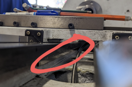
I have a standard modern 2000 series, I am a bumper as well when I am chambering. I currently have my cross slide DRO on the tail stock side which takes away a lot of room from the tailstock. I was thinking of adding extensions so I can install dro out the back of the machine, then you will need more clearance back there for travel!! Anyone have any pics or tricks of how they are doing it?
 
I have a standard modern 2000 series, I am a bumper as well when I am chambering. I currently have my cross slide DRO on the tail stock side which takes away a lot of room from the tailstock. I was thinking of adding extensions so I can install dro out the back of the machine, then you will need more clearance back there for travel!! Anyone have any pics or tricks of how they are doing it?

Quite a few of us (including me) are putting the scale INSIDE the cross-slide!


That linked post includes another link to a bigger discussion.
 
Quite a few of us (including me) are putting the scale INSIDE the cross-slide!


That linked post includes another link to a bigger discussion.

That’s where I’m heading on my SM1120 Series 2000 and it’s moving up the priority list in recent days. One detail I have to resolve is how to accommodate a taper attachment. I’m going to have to roll my own on that since the machine didn’t come with one.

I’ve already done en embed on the cross of my Myford Super 7.

D 😎
 
One detail I have to resolve is how to accommodate a taper attachment. I’m going to have to roll my own on that since the machine didn’t come with one.

I think that's a HUGE ADVANTAGE for you. I have to fit my sensor and some of the scale into my taper attachment. You have the luxury of designing your taper attachment to work with your scale and sensor.

I'm not by any means calling it simple. Just that you can design the two of them to work together and I think that should provide you with more options.
 
I think that's a HUGE ADVANTAGE for you. I have to fit my sensor and some of the scale into my taper attachment. You have the luxury of designing your taper attachment to work with your scale and sensor.

I'm not by any means calling it simple. Just that you can design the two of them to work together and I think that should provide you with more options.

True but with a couple of buts: First if I already had a TTA then I would know what I have to work around or second, having to design a TTA while doing my DRO install just provides the opportunity for procrastination and moves the schedule to the right.

To quote Dylan Hunt: “It’s never easy” lol!

D 😎
 
Back
Top