• Scam Alert. Members are reminded to NOT send money to buy anything. Don't buy things remote and have it shipped - go get it yourself, pay in person, and take your equipment with you. Scammers have burned people on this forum. Urgency, secrecy, excuses, selling for friend, newish members, FUD, are RED FLAGS. A video conference call is not adequate assurance. Face to face interactions are required. Please report suspicions to the forum admins. Stay Safe - anyone can get scammed.

spindle bearing fitment and retention

If you ever care to share a sketch, coffee stained napkins with ballpoint scribbles... I'd love to have a look. Now if I need a grinder to make a spindle to grind then I should probably pass anyways LOL

Quite a while back I bought a book: Spindles by Harprit Sandhu - workshop practice series #27. I pull it down once in a while & then put it back again. Its hobbyist orientated which is fine if generic layouts is all you are after. But its very light on technical details - what is to be supported, how big or small is enough, what floats & by how much.... I can kind of trace how loads are being transmitted & compensated but that's a far cry from understanding. Maybe there are engineering text books on the subject but that's kind of the issue - a rather wide informational gap in between basic & high end.

Clough published his TPG spindle which looks generically like others including the Sandhu book. OK, in the final episode it spins & he made a surface shiny before moving onto another project so I really don't even know how it compares in the grand scheme.

I'd like to see what's inside a (was it a Deckel?) spindle head Stefan adopted to his tool post in a very early video. Its these small compact ones I'm most interested in. And I keep wondering if these ER shafts couldn't somehow be adapted. The one I got for my TCG Franken-spindexer seems decently high quality, at least compared to what I could make. I should stop, I'm imposing on Toronto's thread

For sure, there is not a lot too them, inevitably they follow a few basic patterns like the bearing catalogue show. I'll post below a cross section of the spindle I made to replace the one of the Aciera F1. I did a detailed thread on, but it looks like the photos have all been cropped. (I'd consider fixing it, but can't edit the posts .... grrrrr .... I hate when sites do that and the only beef I have with CHMW)


The world has (imo) changed regarding bearings, and that should affect design. The accuracy achieved with their uber expensive super precision cnc grinders has changed over the last few decades manufacturing. I have had conversations with two engineers at two of the larger manufactures who have told me manufacturing is so consistent and to such small tolerances that the bearings of different classes, (e.g. P4 vs P6) all come out of the same production lots. The higher cost of a P4 is the time it takes to certify their tolerances not that its production is any different. It is possible that when grab a bearing from the barrel to certify as P4, there are rejects, however these guys suggested its not like that .... that things are dialed in enough that they are all coming out meeting P4 standards (after its not that big difference).


This also holds true with AC preloads. The tradition way is to either buy match pairs or grind inner and out race spacers of very slightly different lengths to create the preload you want. I've done it, and adds to the time and fussiness of a project. You have to have a very accurate grinder (difference in length might be 1 1/2 tenths or so). YOr spend 10x as much for a matched pair. Now, with quality of manufacturing, the "universal" fit bearings spend $80 instead of $800, slap them together it get great preloaded performance.

Another example, once upon a time you spent a fortune for a Barden deep groove bearing at the pulley end ..... now you buy an SKF stand deep groove for small dollars and it gives P4 like performance.

So ...... cost barriers that once influenced are greatly reduced. i.e. why not use angular contact bearings back to back with a outboard deep groove bearing supporting the pulley? It just doesn't cost that much more nowadays.

AC shaft arrangement.jpg


Here's a typical one using magneto bearings. Not sure they were used instead of AC's. The spring creates the preload, using AC would better than the Clough design imo and as per above, the cost differential (using universally patched bearings) has shrunk considerably

1734707096759.png


Here's the one I did as an Aciera replacement. The AC's are so small because it was an extremely tight envelope between the housing OD and the W12 collet


cross section F1 spindle.jpg


and the results


MWZ_8433-1300x866.JPG


that isn't by the screws, just a bit of oil :)


20240623_085340-700x700.jpg


20240623_125854-1300x1300.jpg
 
Last edited:
@Mcgyver this is similar to how I've started measuring my cross bed feed while grinding. But mine is a 10ths reading analog dial. It opened my eyes when I started using it. Initially it was installed for accuracy & DOC setpoint to get dials & DRO out of the equation. Even the act of locking the ways can have an effect on setting position; set to zero, lock the ways, oh nice it moved to +0.0004" . But the big revelation was its a rudimentary vibration meter. Once the grinder motor is powered on, the needle becomes a back & forth flurry displacement of a thou or so. Interestingly the DRO at 0.0005" increment setting do nothing, same number. I don't think the surfaces can possibly be displacing this amount especially at high frequency, but I think vibration is pulsing through the indicator needle/mechanism. I guy who I followed doing very high end TPG on a much better lathe says some is normal but it should ideally be low. He also McGyvered his lathe so its high precision rework & the locks were modified/improved. I think my issue is a top heavy motor sitting on a wedding cake of sliding surfaces from the compound to the cross slide to the bed to... on a gearbox driven Taiwan lathe. I might just be the limit of what can be reasonably achieved. I mean its certainly better than turning but it cant compete with a dedicated grinder which weighs 4x more than my lathe. But yur vibration dampening comments caught my eye, that's what I was going to play with next.

1734708665069.png
 
> Here's a typical one using magneto bearings.

Useful sketches & info thanks. Hmm... I less enthusiastic about my notion of utilizing those commercial hardened/ground ER spindle extension shafts. I'll have to ponder the AC configuration now that I see your flavor. I was considering the adaptability to what you call magneto bearing style. But reworking/adapting a commercial ER shaft may outweigh what I thought could be benefits: come in different useful lengths & ER size formats, hollow shaft at least in the ER area, collet seat & threads already ground & concentric, supposedly 0.005mm if you believe the stated specs, nominal shaft OD's that presumably would match standard metric bearing ID's or at least be within lapping range if slightly oversize. Not sure how easy OD machining (threading) would be, but maybe there is a workaround. For my purposes I'm actually trying to avoid collets which is just more home shop tolerance stack-up issues.

1734711057932.png
 
> Here's a typical one using magneto bearings.

to what you call magneto bearing style. B

Magneto is a specific type of bearing, not as easy to find so my guess is they are less common than they once were. I've seen them mostly in TPG spindles. I think the DB200 unimat has them but the later U3 switched to deep grooves preloaded with belleville washers. They're a bit like an AC, but will come apart. You can't easily replace them with AC's as the sizing is different. If starting from scratch, I'd go AC's.

this is similar to how I've started measuring my cross bed feed while grinding. But mine is a 10ths reading analog dial.

Good eye. that indicator is tenths reading, but being digital is oh so convenient to switch to metric when doing bearing fits (the most demanding work I encounter). A DRO on lathe can be tricky to fit without giving up some functionality (it's in the way of something) where as this bolts on when needed and is tenths accurate

there's also these things that I made. The are spring loaded cylinders and can either push or hook onto and pull on the cross slide - puts a preload on the nut in which direction. They mount to the piece that clamps to the dovetail that holds the indicator. Breath on the the lathe and it seems like you change a tenths indicator reading, but this preloading helps a bit.

You still have to hold your tongue just so for best results.

1734715421770.png
 
Last edited:
Magneto is a specific type of bearing, not as easy to find so my guess is they are less common than they once were.
Ahhhh. I knew they were a type of separable bearing which I just assumed was important for that reason. But I never really understood why a comparable tolerance class modern day deep groove bearing couldn't be used in a spindle, at least using that pre-load method. I'm not too familiar with magneto's (if that's where the primary implementation derived from). They didn't strike me as a particularly demanding bearing installation other than maybe the separable feature for some reason? The things we think we know, only to discover we really know JackSh*t.... a famous Hobbyist

1734716466995.png
 
Ahhhh. I knew they were a type of separable bearing which I just assumed was important for that reason.

I don't know the history, only that I see them in places where I'd install AC's - i.e. radial and axial loads. AC's are readily available in a variety tolerances.... afaik you are not going to find P4 magnetos for example and you may be restricted to mystery ones (don't know of any big companies make them anymore). I have only seen them in spindles but agree they were light spindles and spindles where fixation via a spring was good enough (not for milling imo). btw, deep grooves have been used for spindles. The unimat 3 for example and even going to the high pedigree stuff, Boley did so with their venerable WW83 and WW82 lathes. (I've got an 83 and did convert to P4AC's as in that instance the size was plug and play, thought the lathe worthy of it and you can't easily get P4 deep grooves.... but Boley, who has never been accused of making junk, shipped it with deep groove ball bearings (of a high class)

They didn't strike me as a particularly demanding bearing installation

Me either, but any bearing demands a lot of accuracy. Especially in higher classes, P4 etc. To much interference, and we're talking tenths, and you'll wreck an expensive pair of bearings when you press them on. No exaggeration (don't ask how I know, I'm in a good mood so far today lol).

As a general comment (not directed at you) I don't think its well appreciated how much you change geometry with interference fits. For example, Schaublin tooling is locked on a threaded spindle just by a collar that tightens on a solid section of the chuck (photo below). Taper fit roller bearings are fit (to microns) by how you far you drive up them up the spindle taper and so on. Force a P4 AC on a shaft a tenth out tolerance and it could be trouble.

Note to self..
SKG Bearing 71902 Cd/P4ADGA ~$630 + HST.

That is for a matched pair it seems ..... price out two universal preload P4's and it will be fraction of that which as per a few posts above, imo will pretty much get you to the same place.


20220213_095706-700x340.jpg
 
Last edited:
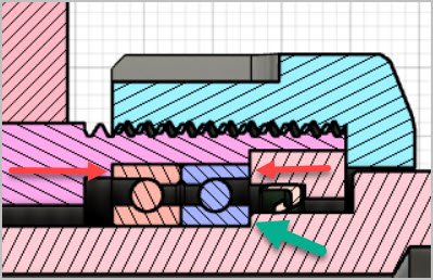
@Mcgyver so onto the ACB spindle now. Am I correct in assuming the outer race retaining nut is squeezing the ACB set (left blue arrow) & ACB set is constrained on the right by the housing lip (right blue arrow). Isn't that the only prerequisite to ACB preloading? (tighten the outer races until the faces meet). I guess I'm asking what is the role of inner race retaining nut (orange) which appears to contact aft race inner face but has clearance everywhere else because I don't see its equivalent in the generic bearing sketch. And just as a typical working number, what kind of shaft tolerances are required for ACB bearings around this size?

1734728450648.png
1734728954622.png
 
Isn't that the only prerequisite to ACB preloading? (tighten the outer races until the faces meet).

I'll say no, but I may not be understanding what you mean. In both those designs the inner races are held tightly between a should and nut on the shaft, and the other races between a shoulder (on mine, other one is a retaining clip) and a nut screwed into the housing. Both must held solidly. The preload is created by a slight difference in the widths of the races where the mate to each other. This difference in races pushes the balls into corner when you tighten the inner race and out race.

I had been working on a write up of these spindles and did the graphic to try and illustrate it (exaggerated of course). Imagine two AC's with no preload ground into the race, shown in A. Apply all the force you want to the red and blue arrows, and its not going fix things axially. It will move by X, the clearance the balls see between the two opposing corners.

However, if spacers are placed between them, with a difference in length of 2X, applying forces to red and blue solidly pushes the balls into the corner, no more axial movement. How much preload you get is engineered in to the difference in the space length. I can remember having to grind spacers to preload them, or buy the super expensive matched sets John posted. Then it seemed like everything moved toward "universally matched", (or maybe just my understanding evolved.) where you didn't have to buy match or grind spacers to get a preload.

what kind of shaft tolerances are required for ACB bearings around this size?

The ones in my drawing are 71804's with an OD of 32mm and an ID of 20mm. On the shaft (where the interference fit is) the diameter as SKF called for it worked out to .78740" + .00004" - .00012" so about 1.5 tenths total range. I did buy super precision matched bearings for this spindle. Nerve racking work given how hard it is to hit those tolerances and how expensive a mistake is.

Which I made. I'll come clean. To work that accurately I used a T&CG in perfect condition (scraped by yours truly) with a motorized workhead. I've got it dialed in so it's doable to grind to a tenth and do so along a length. I used an indicating mic set with a gauge block, all Mitutoyo, in an attempt to get the highest level of measurement accuracy that I could. I nailed the dimension for the AC's! Well within tolerance. Pressed it on, and it was stiff and crunchy to rotate.

Turns out that while I did have a small relief grove and did measure properly, I didn't measure all over the length. Wheel wear had the shaft 1.5 tenths too big right at the end and that wrecked the bearings. A big wack with a very expensive stupid stick. I was able to recover the shaft (very carefully set up and ground that little bit into tolerance) get new bearings and try again. What I should have done, and know to do, is angle the wheel, a degree or so, so that its only cutting at the leading edge.

That may be true if you shop around, but the same individual bearing in the same series is $307 at my local distributor

My mistake, I did say P4 but thinking was originally to compare them to regular AC's, not the super precision P4's ..... because ..... P4 vs P5/P6 should be as accurate (but not certified as such as per my earlier post) AND that with the universal match you no longer have to by matched sets (only available in the high priced P4s or P2 as I understand it) to get a preload without grinding spacers.

YMMV. I'm blabbering on like the world spindle bearing authority; which is not the case. I've designed and built a couple which required study so just sharing what I think learned through that.


ac preload via spacers.jpg
 
Last edited:
My understanding (probably incorrect) is one can choose AC's whereby the preload amount can be set/altered within their defined limits by combinations of setting rings, spacers etc. Maybe that is what you are showing/utilizing?
1734746196901.png


Or (maybe where I'm confused) as matched sets whereby the preload / clearance is defined in the catalog & they figure out the ring widths & other details such that you mount them, ensure they are brought together face to face contact & that achieves the catalog preload rating.
1734746277295.png
1734746387430.png


I think there is yet another, double row maybe? But I'll leave it at this for now. I have no idea if its one of those, yes they are available but it will cost you $1200
 
Well the learning curve is high when dealing with bearings, shaft fits, and resulting? accuracy. One thing I have noted in some/my bearings books is angular contact bearings can be put in either way — I will call it face in or face out, depending on preload adjustment being on the shaft or the housing. However you need to remember to have a bit of allowance for the race you are adjusting to move, inner/outer.
And I am no expert either, the bearing books are full of info. @Mcgyver, are the inner bearing races drawn wrong on the “A and B” drawings or are they a type of angular contact bearing , I have not seen/not remember?
I am working on a spindle for a milling machine, another project on hold at the this time, along with most of very many.
 
are the inner bearing races drawn wrong on the “A and B”

Yes, inner race is incorrect. It's more an illustration to show what preload is and how you get it. I might be making this up as it was a while ago, but think I started with a 3D model from somewhere, maybe Mcmaster or SKF, and took a cross section and modified it to show the clearance in the other race to make the point
 
Back
Top