• Spring 2024 meetup in Calgary - date Saturday, April 20/2024. discussion Please RSVP Here to confirm and get your invitation and the location details. RSVP NOW so organizers can plan to get sufficient food etc. It's Tomorrow Saturday! you can still RSVP until I stop checking my phone tomorrow More info and agenda
  • We are having email/registration problems again. Diagnosis is underway. New users sorry if you are having trouble getting registered. We are exploring different options to get registered. Contact the forum via another member or on facebook if you're stuck. Update -> we think it is fixed. Let us know if not.
  • Spring meet up in Ontario, April 6/2024. NEW LOCATION See Post #31 Discussion AND THE NEW LOCATION

Rotary Broach

RobinHood

Ultra Member
Premium Member
After having seen Randy Richard in the Shop and Stefan Gotteswinter build their Hemingway Kit rotary broaches, I decided to take a crack at making one.

First I went in search of some plans online and found one that I liked as a starting point.
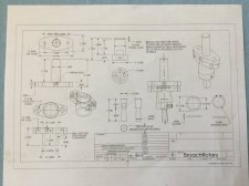
IMG_0795.JPG

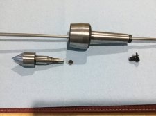
Then I had a look around the shop for parts and bits of metal that might be suitable to be turned into the various components. The live center (LC) on my lathe tool holder rack caught my eye. Perhaps one could base the broach on the same basic dimensions/functions? It has a rotating part held in a body which is attached to either a driver (like a milling machine) or held stationary like in a tail stock. So now I needed both MT3 and R8 shafts on the driver plate - not just the straight shank that I had originally planned. Well, looking around some more, I had one of each from boring heads that have screw-in adapters.

Here is the MT3 live center disassembled that served as a template for the rotary broach.
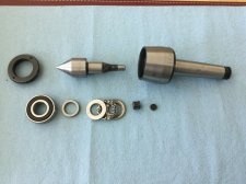
IMG_0792.JPG

So if one took the LC spindle and made it hollow to accept cutting tools as shown below, that would be the tool holder taken care of... (4140 steel)
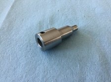
IMG_0799.JPG
The basic dimensions of the tool holder are identical to the spindle from the LC. The tail is a little shorter to reduce the overall length of the rotary broach. I used the same three bearings as in the LC: one ball, one ball thrust, and the little roller for the end. The set screw hold the tools.

Next I made the body from a piece off of a 4140 log. The four holes on the flange are oversize for a 1/4-20 SHC to allow for adjustment of the tool point to the axis of rotation. That way it just wobbles, but has no run-out. The set screw is for oiling the bearings.
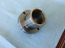
IMG_0801.JPG

Here is the body from the back with the key way.
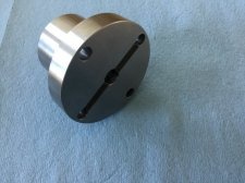
IMG_0802.JPG

The body of the broach needs to be mounted at an angle to the center line (the drawing suggest 1.2*- I went with that). So I made the drive plate (also 4140) with a 1.5 in by 18 tpi threaded hole to accept the interchangeable adapters (MT3 and R8) and milled and ground the other face 1.2* off of parallel.
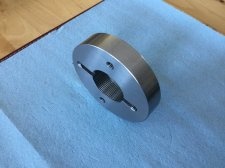
IMG_0803.JPG
Note the corresponding key way to match the body's to transmit the driving forces using a square key.

Here is a side view showing the 1.2* taper of the faces.
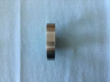
IMG_0804.JPG

And to hold all the parts inside the body, here is a retaining ring with face spanner holes.
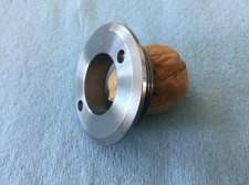
IMG_0800.JPG

These are all the parts in one image. I did not make the arbours.
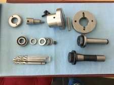
IMG_0793.JPG
I have good supply of broken HSS drill bits and Carbide end mills from my daughter's work . I will be making broaching tools from them as I need them.

Lastly, the broach fully assembled.
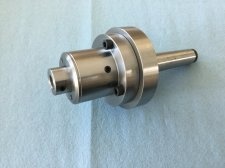
IMG_0794.JPG

This was fun to build and I learned a lot. Now I just need to make a broach and try it out...

Another project off my very long list of things to do complete.
 

PeterT

Ultra Member
Premium Member
Very nice! And smart utilization of other components. Look forward to your broaching results.

Seeing this, I'm also interested in the live center disassembly. Looks like on that particular one the front face comes off with that special threaded cap with 2 pin hole wrench? holes? Then the bearings etc. Did things generally slide or some press work? I'll have to look at mine again but at first glance I don't recall that. It obviously was assembled but it looks rather sealed.


For another interesting Hemingway design/kit check out floating reamer holder by this fellow.

https://www.youtube.com/channel/UCEu2MvQKiTvi7XSl26cn6AQ
 

RobinHood

Ultra Member
Premium Member
Seeing this, I'm also interested in the live center disassembly. Looks like on that particular one the front face comes off with that special threaded cap with 2 pin hole wrench? holes? Then the bearings etc. Did things generally slide or some press work? I'll have to look at mine again but at first glance I don't recall that. It obviously was assembled but it looks rather sealed.

Yes, this LC uses a face spanner as well to take off the front cap. Also, if you zoom in on the picture with the LC, there is a slotted screw covering the tail end of the MT3 drawbar hole. (It is backed out just a bit in the pic; it protects the threads and helps eject the LC from the tail stock). One removes that and then you can insert a small rod from the back and push all the parts out the front, Yes, there is a through hole in the MT3 part. Again, zoom in on the pic, you will notice a little black disk to the right of the roller bearing in the exploded stack-up of the internal components. The rod actually pushes on that and thus does not damage any parts as you use a dead blow hammer (or a small arbour press - which I don’t have) to press it apart.

Here is a picture of what I am talking about above...
EE6AA5C9-BB67-4515-BDC7-BF2D95B5B609.jpeg

That floating reamer holder looks very interesting. I don’t have any MT shanked reamers though; only straight shank aka chucking reamers. Would have to make an adapter for a chuck. Actually, I would also use the interchangeable MT3 / R8 combo for the tail end, like I did on the rotary broach....
 
Last edited:

RobinHood

Ultra Member
Premium Member
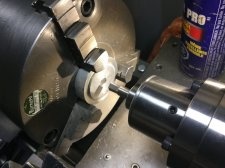
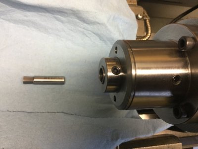
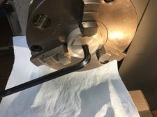
Finally got around to making one broach and try this thing out. It is a 5/16” hex. It is the closest to the shank diameter of the broken drill bit I am using. Thus the least amount of grinding was required. I’ll make more now that the T&C grinder is operational again. The old belt gave up the ghost and the spare ones that came with the grinder had the PU coating just fly off because of their age.

Here are some pics. I just quickly tried it in a piece of 6061 in the lathe. Ran it at 350 rpm. It took very little pressure to get 1/2” deep into the hole. The real test will be in steel....

3E1CFD96-7911-40EA-A891-79B7CF145727.jpeg

CBEEADCF-1E37-4DB1-8837-7A8CEE0DFCE8.jpeg

ED518564-74F6-4CBB-96C6-644281F82F4F.jpeg
 

Jimbojones

Active Member
Cool. I'd like to see it in action

Do you think you could use them to clean up some existing socket head bolts... or would that be too hard of material? I'm talking about just truing up the bottom of the hole to ensure full-length engagement
 

RobinHood

Ultra Member
Premium Member
Do you think you could use them to clean up some existing socket head bolts... or would that be too hard of material? I'm talking about just truing up the bottom of the hole to ensure full-length engagement

It might be too hard for HSS. I might have some solid carbide end mill shanks that could work. Let me try it. I’ll report back....
 

PeterT

Ultra Member
Premium Member
Coincidental timing, I was just turning some socket screws on the lathe & experiencing some variation. The OD of the heads & shank area were turning nicely but they sounded different across the hex area. Not just interrupted cutting but felt like different hardness. Supposedly they are hardened & oil quenched to 33-39 HRC which doesn't sound all that hard. But maybe when they forge the hex impression that localized area might be a bit different? Or it could have been a bad batch of tuna cans in this particular billet :)
 

RobinHood

Ultra Member
Premium Member
Pardon an amature question...how is the diameter (cross the flats) of the broached hole controlled?

No worries.

I use a Tool And Cutter grinder with a cup wheel. I present the blank at 88* to the spindle axis of the grinding wheel in an indexer. The centerlines if the blank and the wheel are at the same height. In this case the 88* gives me 2* of relief on each flat (90*-88*=2*). We move the blank forward past the wheel for the required lenght of the flat - 1/2” in this case. My blank has a nominal diameter of 10mm (9.7mm actual). So I just ground all six sides (by indexing around) until I had a complete hex shape on the face of the blank. Then I just measured with a mic to see how close I was to 0.3125 (the 5/16” broach I was making). Say I was over by 0.020, I would infeed axially to the spindle by half of that (0.010”) because we are going to grind all six flats by that amount in one more pass around. So now the distance across the flats is what I want.

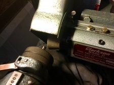
Here you can see the cup wheel and the blank sticking out of the indexer. The indexer (and thus the blank) sit on a sliding table that can be moved forward/back across the cup wheel.
730242A5-6D5F-4556-AB00-70772CF1331D.jpeg

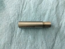
Finished 5/16” broach
63804C0C-79F8-414A-99C2-00E82CD2CF85.jpeg

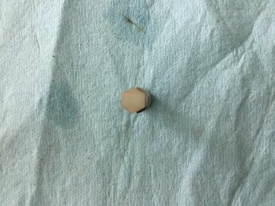
End view of the 5/16” hex broach
651129FD-4AA6-421F-B7F2-6506B1B85FBE.jpeg

It is similar to turning on the lathe with dials that read in radius. Whatever reduction in diameter you need, just take half of that in the radius.

The maximum size of the broach is limited by the blank’s diameter as the finished hex ( measured across its points) can’t be bigger than the blank diameter.
 
Last edited:

RobinHood

Ultra Member
Premium Member
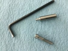
In a previous picture above you can see the off the shelf black SHCS used to hold the body to the drive plate. They work, but are about 1/4” too short. They are 1/4-20 by 1”, 3/16” hex drive.

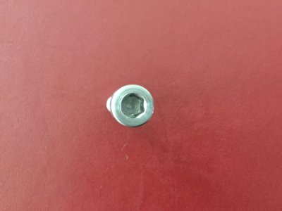
To see if my RB would work in steel and how much more force would be required to broach the hex, I decided to make one 1/4-20 by 1.25” SHCS from tool steel.

Here’s the result...
4681B01C-AD8B-49AE-B4DE-B43BA6E4CBD0.jpeg

This shows the hex in the head. There are just tiny chips left in each corner at the bottom of the hole as I went back in with a drill to clean out the big chunks after broaching
657B0DBD-227D-4074-A198-F06CB4630D77.jpeg

It took more effort to push the broach in the steel compared to aluminum, but not nearly as much as I thought. This is only a 3/16” hex and I’m sure bigger ones will take more force. I would compare the force required to broach about equal to drilling a hole with a dull drill bit of the same size.

Now I have to go make the other three SHCS to complete the set for the RB....
 

RobinHood

Ultra Member
Premium Member
Thanks for the link PeterT.

A very nice tool indeed. I especially like his compact, adjustable indexing head he can set-up in his vice. I have all the same capabilities with my universal dividing head, but it is just too big for the surface grinder or the mill in other than a longitudinal orientation...
 

PeterT

Ultra Member
Premium Member
Yes, I like his design style, functional & clean. I noticed he favors 'pre-hardened 4140' for a lot of his tooling. I've never worked with it before, but I'm intrigued.

As an aside he has a website with same his tool collection as on link. I bought his tool post grinder spindle plans for 5$. One of my to-do projects is to make a mini version so wanted it as a guideline.
https://rossbotics.wixsite.com/machiningtechniques
 

DPittman

Ultra Member
Premium Member
Just wondering if @RobinHood had any updates to his rotary broach version and if carbide tooling bits were successful. I'm thinking I would like to try the hemingway kits version as it looked simple enough. However I don't have a grinder and don't know how I would manage making the broach bits yet.
 

YYCHM

(Craig)
Premium Member
Just wondering if @RobinHood had any updates to his rotary broach version and if carbide tooling bits were successful. I'm thinking I would like to try the hemingway kits version as it looked simple enough. However I don't have a grinder and don't know how I would manage making the broach bits yet.

Got a link to this hemingway kits version?
 

RobinHood

Ultra Member
Premium Member
I have not made any carbide tooling bits. HSS worked fine so far.

Yes, having some form of a T&CG is pretty much a requirement when planning on making your own bits as that is the only way to accurately grind the very shallow relief angles and index the number of cutting surfaces.

Hemingway kits have a good reputation. It would be a fun build of a useful tool. Not sure it they take commercially available tool bits.
 

DPittman

Ultra Member
Premium Member
Got a link to this hemingway kits version?
The only website I found for the Hemingway kits was in the UK I think. But YouTuber Randy Richard does a nice series on the Hemingway kit build. Stefan Gotteswinter also has a few videos of it as well.
 

Tom O

Ultra Member
Somewhere on one of my puters there are plans for a rotary broach I’ll see if I can track it down it was made and posted by a member on Madmodders.
 
Top