• Scam Alert. Members are reminded to NOT send money to buy anything. Don't buy things remote and have it shipped - go get it yourself, pay in person, and take your equipment with you. Scammers have burned people on this forum. Urgency, secrecy, excuses, selling for friend, newish members, FUD, are RED FLAGS. A video conference call is not adequate assurance. Face to face interactions are required. Please report suspicions to the forum admins. Stay Safe - anyone can get scammed.

Rongfu round column mill VFD install.

Here are the pieces I bought. The motor is a 2 HP, 240v, 3-phase Baldor motor, replacing my previous 1/5 HP 240v, 1-phase Princess Auto motor. The VFD is a Square-D (Schneider) Altivar 18, rated for 240V and 1.5KW (2 HP) that was surplussed from an industrial installation. Both pieces are well used, but I bench tested them and all seems well. The only hiccup so far is the cooling fan on the VFD which was missing some or the fan blades. It was bit unbalanced and noisy upon startup, and then it self destructed after a short period of time. Got a replacement from Digikey for about $25, so not too upset about that.
 

Attachments

  • VFD_Parts.jpg
    VFD_Parts.jpg
    127.6 KB · Views: 5
The motor is currently controlled by a magnetic starter. There is a switch behind the starter to turn on/off the mist cooling system. The mist cooling system comprises the switch, a solenoid and the mist cooling block itself, as shown below.

Mist_Cooling.jpg


On the right side of the mill head is a switch that provides power to the spindle LED lighting and the DRO.
LED Switch.jpg


My plan is to consolidate all these control as much as possible. I want a single on/off switch to control power to all of the mill systems, plus a control panel that is used for motor on/off, direction, speed, cooling.
 
One detail that I noticed in my testing of the the VFD is that it will return power to the drive upon a power outage/restart. So if I use a simple toggle switch to control the motor power the drive can restart itself after a power outage, which is... less than desirable. So my plan will be to use a momentary switch to turn the power on, with a latching relay to maintain power. That way, a power outage will drop out the relay and the drive will stay off when the power is turned back on.
 
 
I've been reading through your thread, YYCHM; quite informative. I'm planning to mount my VFD and control panel onto the left hand side of the mill head, so aiming for as small a drive package as I can manage. Looks like everything will fit, and I've already made some of the custom boxes/mounting brackets I will need. Pictures of that tomorrow.

And, I should note... your thread really piqued my interest where you installed a power feed to the table. I got a similar looking unit at an auction site for little $ and I am planning to mount it to my mill. It's supposed to mount to a Bridgeport mill, so some massaging will be needed,... probably similar to what you went through.
 
I'm going to mount the VFD where the magnetic starter currently sits, with the control box in front, above the spindle lock. The VFD is wider than the magnetic starter, and the column crank will have to be moved outward to make this all fit. The stock crank handle looks like this:

Column Crank.JPG


I fashioned a shaft extension from stock I had laying around the shop:

Column Crank Extension.JPG


Now the re-positioned handle will give the room I need:

Column Crank Extended.JPG
 
The control box, which will reside above the spindle lock handle, will control all functions related to the drive. GIven the space constraints, a 2-wide, 3-up patten for the control buttons is best. I've chosen Schneider control buttons for this project, and I can't fit that arrangement in readily available single-gang control boxes. So I'm going to build a custom box from shop scrap pieces.

The control box will have these discrete controls:

START: A green, normally-open, momentary push-button. The VFD provides 24V DC power for the controls. When I press this button it will feed 24v to the LI1 (logic input 1) or LI2 pins on the VFD control terminal strip, which initiates FWD or REV motion of the motor. The issue I found previously was that if I use a simple toggle switch for this control then after a power outage the drive would restart itself when power returns unless I remember to manually turn the switch off. I don't like this behaviour. So I chose a momentary button, which requires me to latch the drive signal ON with a small relay. Now, when power is cut, either by the STOP button or a power failure, the relay will drop out. I bench tested this logic on the drive using a 24V relay I had on hand. Worked fine, but that relay is much too large and it draws 60ma. The 24v control supply is limited to 100ma, and I need to drive another relay for the mist cooling control, so I got a couple of small Omron relays from Digikey that only draw 8.5ma each. They cost less than $3 a piece.

STOP: Red, normally-closed, momentary pushbutton. Breaks the 24v control signal to the drive, dropping out the latching relay, so all motion stops.

DIRECTION: A 3-position, maintained switch. Feeds power from the latching relay to either LI1 or LI2. The middle position breaks the 24v signal to those pins, so is the same as a stop command.

SPEED: A 10K potentiometer attached to pins +10V, COM, and AI1 (analogue input 1) on the drive.

COOLING: I'm going to use a small toggle switch for this one. I want it to be visually smaller than the drive control buttons, so that it distinguishes itself as a 'lesser' control. It will be tied to the signal from the latching relay, so that cooling will only be turned on while the FWD or REV drive signal is present; no need to be spraying cooling fluid around when the mill isn't chewing any metal. The cooling solenoid valve is 12v, and consumes a bit of power, so I cannot drive that directly from this control signal. I already have a 12v power supply that drives the spindle LED ligting, so I'll feed this control signal to a relay that will piggy-back off that power supply.

FUTURE: There is room for an additional button in the control box. The VFD offers a JOG feature, but I'm not sure I need that right now, so I'll just leave a blank spot on the control panel.
 
Thanks, Mike, I did see that part of the manual. First thing I did was a factory reset. Then I checked that value and it is, indeed, set to ‘no’. But it does restart if the 24v signal is present on LI1 upon power up. So I decided to go with momentary switches to be safe.
 
Here are the pieces I bought. The motor is a 2 HP, 240v, 3-phase Baldor motor, replacing my previous 1/5 HP 240v, 1-phase Princess Auto motor. The VFD is a Square-D (Schneider) Altivar 18, rated for 240V and 1.5KW (2 HP) that was surplussed from an industrial installation. Both pieces are well used, but I bench tested them and all seems well. The only hiccup so far is the cooling fan on the VFD which was missing some or the fan blades. It was bit unbalanced and noisy upon startup, and then it self destructed after a short period of time. Got a replacement from Digikey for about $25, so not too upset about that.
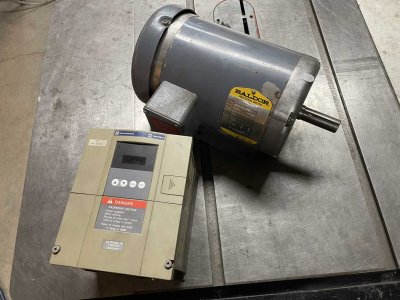
Good plan. I have done exactly as you are doing with great success. Zero failures with used motors and used Altivars. I'm not sure but I think the 18 supports both a breaking resistor and SVC those are the cherry on the sundae features. FWIW my used non VFD rated motors run as cool as a cucumber even at low RPM.
 
The 18 does have terminals for a braking resistor, but in my testing I don't think it will be necessary. I set the deceleration rate to 3 sec and it very nicely winds down the spindle from full speed. It's fast enough that in the time between poking the stop button and picking up the collet wrench the spindle would be fully stopped. Surprising how annoying it is now to use my old 1-phase setup and wait for the spindle to stop naturally.

And I'm expecting this Baldor motor to give me a lifetime of service,... well, my lifetime anyhow. ;) I don't expect it to get near the 2HP rating anyhow, given the small work that I do.
 
I assume you know that they will run cool with no load. It's when they are loaded that it becomes an issue.

Test was drilling 1" holes in steel, with a regular drill bit. I don't remember how many I did, but at the time I thought hmmmm I should check the motor temperature after and see how it's doing, was ~30C. I was pleasantly surprised. I think for hobby use any old motor is just fine.

Biggest issue was locking the table down, not the motor temperature.
 
Made some brackets to support the drive package and the control box. Both of those will have key-hole mounts, so that the entire drive package can be removed as a unit by only disconnecting the motor.

Control Brackets.JPG
 
Back
Top