• Spring 2024 meetup in Calgary - tentative date Saturday, April 20/2024. Other regions are also discussing meet ups. If you want one in your area get going on organizing it! discussion
  • We are having email/registration problems again. Diagnosis is underway. New users sorry if you are having trouble getting registered. We are exploring different options to get registered. Contact the forum via another member or on facebook if you're stuck. Update -> we think it is fixed. Let us know if not.
  • Spring meet up in Ontario, April 6/2024. NEW LOCATION See Post #31 Discussion NEW LOCATION

RFQ to manufacture spline and shaft

Matt-Aburg

Ultra Member
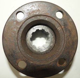
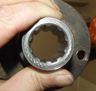
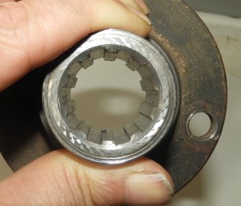
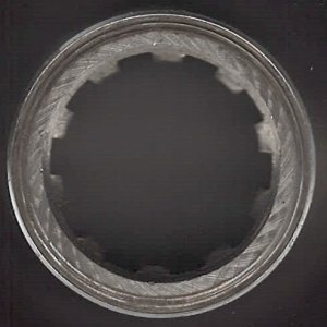
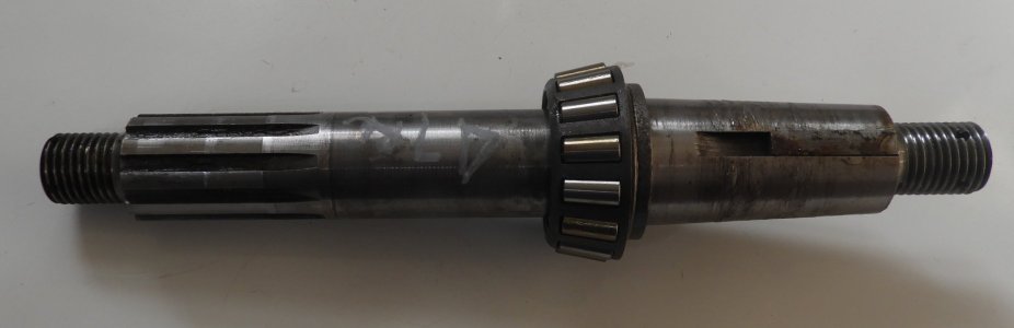
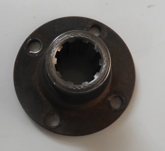
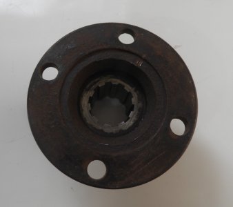
I have two parts that need services I cannot provide. All shops around here will not touch it due to building tooling for Electric Automobiles. The shaft requires a male spline and Key seat, and cylindrical grinding. The coupler requires internal spline cut. The Griffith shop requires 6 sets immediately, with this an ongoing repeat job. I could bump this up to minimum 10 each.

I only have pictures now. A drawing will be made after I get the shop to remove the bearings off the scored shaft. Material must be Heat-treated to 48 RC. I will do research on best material based on what its function is.. At least 4140.
 

Attachments

  • DSCN1598.JPG
    DSCN1598.JPG
    106.1 KB · Views: 23
  • DSCN1599.JPG
    DSCN1599.JPG
    310.3 KB · Views: 28
  • DSCN1600.JPG
    DSCN1600.JPG
    265.3 KB · Views: 26
Last edited:

Matt-Aburg

Ultra Member
What is that part and what is it for?
The parts are wheel bearing shaft for rear hub (This goes in housing I am making). Shaft is cylindrically ground with tapers (2) and OD parallel (1). It has 3/4-16 threads both ends, male spline and also a keyset. The female part fits on the shaft. Looks like just turning then making female spline.

Customer can get parts from England, but wants to avoid Whitworth thread as the nuts cost 16.00 each compared to 1.00 for plate UNF. He is trying to get them made. Inside spline can be wire-EDM or sinker too.
 

Rauce

Ultra Member
Hamilton Precision Inc. is an EDM place I’ve been to. At my old job we would send work to them for unusual features on turbine shafts (old style governer mechanism built into the shaft end).

I dropped off some parts there once and they gave me a tour, really nice little shop packed with EDM machines. Wire EDM, wire hole popper and probably more…

I remember they had a job with internally splined shafts for a marine application when I was there.
 

LenVW

Process Machinery Designer
Premium Member
The parts are wheel bearing shaft for rear hub (This goes in housing I am making). Shaft is cylindrically ground with tapers (2) and OD parallel (1). It has 3/4-16 threads both ends, male spline and also a keyset. The female part fits on the shaft. Looks like just turning then making female spline.

Customer can get parts from England, but wants to avoid Whitworth thread as the nuts cost 16.00 each compared to 1.00 for plate UNF. He is trying to get them made. Inside spline can be wire-EDM or sinker too.
Send me a drawing with the details and I will talk to our machine shop in Woodstock, Friday.
They do a lot of custom shafts, rollers and cylindrical parts.
 

Matt-Aburg

Ultra Member
Send me a drawing with the details and I will talk to our machine shop in Woodstock, Friday.
They do a lot of custom shafts, rollers and cylindrical parts.
I will be occupied for about 1 week with wrapping up small stuff first. I will post the drawing up when it is ready..
 

Janger

(John)
Administrator
Vendor
The parts are wheel bearing shaft for rear hub (This goes in housing I am making). Shaft is cylindrically ground with tapers (2) and OD parallel (1). It has 3/4-16 threads both ends, male spline and also a keyset. The female part fits on the shaft. Looks like just turning then making female spline.

Customer can get parts from England, but wants to avoid Whitworth thread as the nuts cost 16.00 each compared to 1.00 for plate UNF. He is trying to get them made. Inside spline can be wire-EDM or sinker too.
Hi Matt - Just wondering how this would be made. Why is the shaft cylindrically ground? Are you suggesting the shaft and coupler could be made by turning and then the splines added - no grinding required? Could the splines on the shaft be made on a mill with an EM similar to cutting a keyway? Could the female coupler part splines be cut on a die filer?
 

Matt-Aburg

Ultra Member
Hi Matt - Just wondering how this would be made. Why is the shaft cylindrically ground? Are you suggesting the shaft and coupler could be made by turning and then the splines added - no grinding required? Could the splines on the shaft be made on a mill with an EM similar to cutting a keyway? Could the female coupler part splines be cut on a die filer?
I am copying the original as far as grinding. Possibly the grinding is because of the Heat treat and to be absolutely proper on the TIR (they must be co-centric. The splines were cut in prior to heat treat. On the female part, I don't care how its made as long as the spline is correct and fits proper, and is interchangeable. This means they MUST be to specs, which I have yet to determine. These parts should be able to mix and match with any others. (Standard part).
 

LenVW

Process Machinery Designer
Premium Member
Matt,
I had a talk with our machine shop guys and they said ‘no way’.
They seem to have a backlog of projects for this spring.
However,
I did dig up the name of a shop that a former employer had used.


True-Gear Machine Shop
They do a lot of custom splines and similar parts In Cambridge, Ontario.


Contacts:
  • 1629 Industrial Rd.
  • Cambridge, ON,
  • N3H 5G7
  • Toll Free: 1-877-270-9985
  • Phone: 519-653-1301
 

Janger

(John)
Administrator
Vendor
I was curious about the splines. I got reading about various kinds of splines in machinery's handbook. Straight sided splines seem to be more easily manufactured than involute splines. Looks like a straight sided spline could be made with broaching or on a shaper or similar operation on a lathe/mill with a straight sided cutter shaper style. I think these are for fixed applications. The involute splines seem to be more like gears and support rotation. Anybody who understands this better please comment.!

machinerys' h b says: "
Splined shafts are most generally used in three types of applications:1) for coupling shafts when relatively heavy torques are to be transmitted without slippage; 2) for trans- mitting power to slidably-mounted or permanently-fixed gears, pulleys, and other rotating members; and 3) for attaching parts that may require removal for indexing or change in angular position."

I think this project is mainly about situation #1.

There are a number of types according to wikipedia. Here are straight sided splines from machinery's h b


1679195922324.png


Involute splines have a complex shape similar to but not exactly the same as involute gears:
1679196987392.png


@Aburg Rapid Prototype would this part use parallel splines or involute or perhaps one of the other spline standards? It's hard to tell from the pictures.
 

Matt-Aburg

Ultra Member
I was curious about the splines. I got reading about various kinds of splines in machinery's handbook. Straight sided splines seem to be more easily manufactured than involute splines. Looks like a straight sided spline could be made with broaching or on a shaper or similar operation on a lathe/mill with a straight sided cutter shaper style. I think these are for fixed applications. The involute splines seem to be more like gears and support rotation. Anybody who understands this better please comment.!

machinerys' h b says: "
Splined shafts are most generally used in three types of applications:1) for coupling shafts when relatively heavy torques are to be transmitted without slippage; 2) for trans- mitting power to slidably-mounted or permanently-fixed gears, pulleys, and other rotating members; and 3) for attaching parts that may require removal for indexing or change in angular position."

I think this project is mainly about situation #1.

There are a number of types according to wikipedia. Here are straight sided splines from machinery's h b


View attachment 32499


would this part use parallel splines or involute or perhaps one of the other spline standards? It's hard to tell from the pictures.
I would think it is type 1 with a straight side. It is to transmit power. See better photos' below.
 

Attachments

  • DSCN1603.JPG
    DSCN1603.JPG
    653.9 KB · Views: 15
  • DSCN1608.JPG
    DSCN1608.JPG
    477.2 KB · Views: 19
  • DSCN1610.JPG
    DSCN1610.JPG
    405.1 KB · Views: 15

Janger

(John)
Administrator
Vendor
Hard to tell. They look flat but angled to me. With chamfered corners. Matt do you have a flat bed scanner? Try scanning both sides?
 

Matt-Aburg

Ultra Member
Hard to tell. They look flat but angled to me. With chamfered corners. Matt do you have a flat bed scanner? Try scanning both sides?
Here is the scan off a flatbed scanner. I will have to use the 3D scanner to get more details, and not blurry.
 

Attachments

  • IMG_0001.jpg
    IMG_0001.jpg
    72.6 KB · Views: 14

Matt-Aburg

Ultra Member
I guess if the interesting details are not right on the glass it does not work very well.
I will go see my brother in law today. He worked at Colonial Tool in Windsor many years ago doing OD grinding on spindles. He is an expert Toolmaker and might have some insight to add.


Matt-Aburg

Ultra Member
@Janger The female part was broached and is a straight wall as I thought, This was confirmed by my brother in law. He said the broaches he used to grind (manually) would do all the teeth in one shot and were about 2-3 feet long.

The larger diameter inside the flange MUST be a good finish and to proper size. It fits on the OD ground shaft, but slides on. There must be some clearance, but not much.

For a short run production part like this, single slot at a time could be done on a shaper or by other means.... Wire EDM would also do it.
 
Top