• Scam Alert. Members are reminded to NOT send money to buy anything. Don't buy things remote and have it shipped - go get it yourself, pay in person, and take your equipment with you. Scammers have burned people on this forum. Urgency, secrecy, excuses, selling for friend, newish members, FUD, are RED FLAGS. A video conference call is not adequate assurance. Face to face interactions are required. Please report suspicions to the forum admins. Stay Safe - anyone can get scammed.

RF30 head alignment guide

I think that there needs to be means for the arms to adjust to raising and lowering the table.
Agreed. I was imagining the 4 tie rods as you have but minus the collar. The lower two rods tie onto the sides of the table, the upper two rods tie onto the sides of the head. They’re still linked at the rear to give the freedom in Z. Or am I missing something else about how yours works?
 
I miss that press [emoji26]
I think that there needs to be means for the arms to adjust to raising and lowering the table.
Because the table doesn’t have near the same mass or forces acting on it I could see a somewhat simpler setup working well.


Sent from my iPhone using Tapatalk
Maybe, in the case of a floor mounted drill press, securing the head via the motor mount might make more sense. As the head is the large mass introducing the vibration in the first place, and in my case the base is anchored to the concrete floor, this could be a different approach worth some investigation. Certainly attaching the motor mount to the wall is simpler than machining a split bearing (for me at least).

As an annoying colleague of mine used to say, "I need to noodle on that for a while."

Since I retired, I miss some people more than others. He was an other.

1606015362125.webp
 
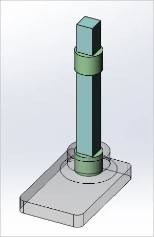
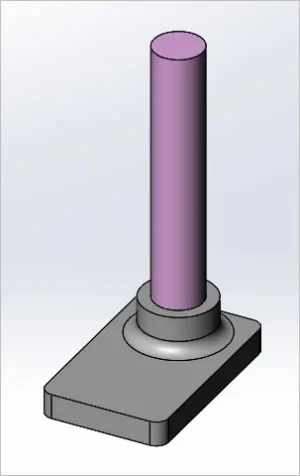
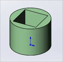
I haven't thought this through & no real idea if the components could be retrofitted like this. But it would be nice if one could machine a round to square adapter insert. The idea is remove the round post, install the adapters into the base, the head & table collar. Hopefully secure it with existing lock screws or maybe it would be pinned. Then install mill a square column that matches the insert ID square. Its not a dovetail but if it was close fitting might be decently accurate. I drew this with a 4" diameter post and a 2.5" square column just as a guess. Not sure how the crank handle / lifting rack would be retrofitted.
 

Attachments

  • SNAG-11-21-2020 0001.webp
    SNAG-11-21-2020 0001.webp
    7.5 KB · Views: 2
  • SNAG-11-21-2020 0002.webp
    SNAG-11-21-2020 0002.webp
    5.5 KB · Views: 2
  • SNAG-11-21-2020 0003.webp
    SNAG-11-21-2020 0003.webp
    3.6 KB · Views: 2
If you have to raise the head on a round column mill it’s impossible to maintain X-Y position because the head is free to rotate around the column just like the table on a drill press when it’s raised or lowered.
This setup prevents the head from rotating as it’s raised or lowered.


Sent from my iPhone using Tapatalk

All clear. When I looked at the pics the first dozen times my eyes told my brain that there were heim joints on both ends, I couldn’t reconcile how that would stop anything from moving

Funny how the mind works.


Sent from my iPad using Tapatalk
 
Mark Winquist of Winky's Workshop 'swapped' in a square column for his drill press. Frankly I thinks it would be easier to build what I did...
 
Aha, I figured someone must have been down this 'square' path already.
Your remedy looks good, David. It should add a lot of stability to head movement.
 
Here is a classic case of round column mill gotcha……...

TooLong.JPG


I was playing around with drilling holes to see how the mill behaved at 30 HZ and ran into this when I switched to Deming bits. My goal was to drill the hole to 1". No choice here, something has to move and raising the head isn't going to save the day.
 
Here is a classic case of round column mill gotcha……...

View attachment 11804

I was playing around with drilling holes to see how the mill behaved at 30 HZ and ran into this when I switched to Deming bits. My goal was to drill the hole to 1". No choice here, something has to move and raising the head isn't going to save the day.

Is it at maximum height?


Sent from my iPhone using Tapatalk
 
I came across another unique way to re-align an RF30 mill head after relocating the head. It involves using a camera mounted on the head.
chrome-extension://gphandlahdpffmccakmbngmbjnjiiahp/http://www.homemetalshopclub.org/news/11/newsletter1107.pdf#page=6
 
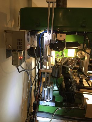
I recently added linear bearings to my LC-30 mill, slightly different approach:
+ 2x4x1/4" rectangular tube, originally was one piece mounted to head and base parallel with column
+ The linear bearings and rods came as a pair, so I used both and mounted them to the rectangular tube.
+ Finally cut the center section of the rectangular tube out

Works well about 0.001- 0.002 depending on how far I lift the head.
 

Attachments

  • LB-b.jpg
    LB-b.jpg
    395.4 KB · Views: 18
Back
Top