• Spring 2024 meetup in Calgary - tentative date Saturday, April 20/2024. Other regions are also discussing meet ups. If you want one in your area get going on organizing it! discussion
  • We are having email/registration problems again. Diagnosis is underway. New users sorry if you are having trouble getting registered. We are exploring different options to get registered. Contact the forum via another member or on facebook if you're stuck. Update -> we think it is fixed. Let us know if not.
  • Spring meet up in Ontario, April 6/2024. NEW LOCATION See Post #31 Discussion NEW LOCATION

project for the day

thriller007

Well-Known Member
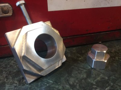
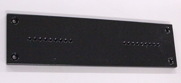
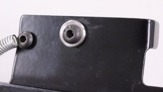
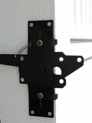
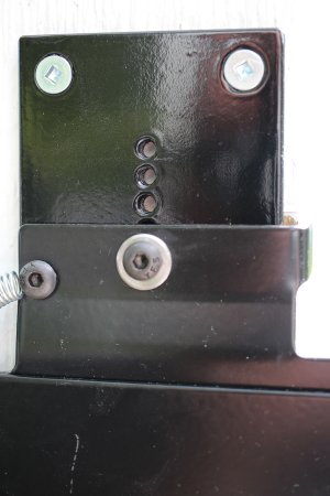
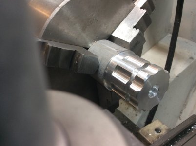
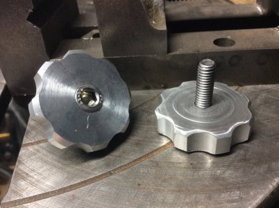
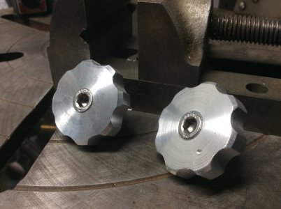
Here is my project for the day. It’s a small indexer for doing four sided six sided or eight sided round stock quickly on the mill. The small adapter I made to go on my bike to adapt a 27mm socket for the rear wheel nut to the 19mm hex that the front wheel needs. I made the adapter before on the rotary table but then saw Mr Pragmatic Lee on youtube building this indexer. Mine is made to accept max 1 1/8” shaft. It is lined up quickly with a square on the table.
 

Attachments

  • 7B611A61-9DCF-452D-AEDB-8F65E430A4CA.jpeg
    7B611A61-9DCF-452D-AEDB-8F65E430A4CA.jpeg
    372.5 KB · Views: 23

YYCHM

(Craig)
Premium Member
It's interesting that you can get away with this considering the jig is eccentric to the stock like it is, but when you think about it....

Thanks for posting, I've been looking for a project. Did you make yours out of steel or aluminum?

Craig
 

thriller007

Well-Known Member
It's interesting that you can get away with this considering the jig is eccentric to the stock like it is, but when you think about it....

Thanks for posting, I've been looking for a project. Did you make yours out of steel or aluminum?

Craig
just out of aluminum. I sized mine about 2.5" wide based on the scrap I found in the shop. Inspiration here
 

PeterT

Ultra Member
Premium Member
Even though I have a pretty solid fence & cemented posts etc. I get a surprising amount of seasonal heave movement. Probably a full inch displacement from low to high over the year which is too much for any latch mechanism to absorb. So it wears the parts, pulls out screws, gate doesn't close, people slam it, dog gets out... I've tried some of the adjustable ones in the past. They are kind of a pivot / hinge / swing allowance but they didn't really suite my installation & I really like this particular latch. Very heavy duty powder coat steel & it clicks nicely (when aligned). So anyways after a head scratching too many overly complicated ideas like jack screws, I came up with this. Usually simple is better. Just a plate of 1/4" HRS with array of 10-24 threaded holes & coat of Tremclad. I machined some stainless inserts bolts to go & marry the existing 1/4" holes. That gives me a little bit of adjustment right there but now, basically whenever the gate moves enough & I can see it straining, I just loosen the 2 screws & re-attach to next increment. Hope it works, this has been bugging me for years.
 

Attachments

  • IMG_4098_edited-1.jpg
    IMG_4098_edited-1.jpg
    135.7 KB · Views: 8
  • IMG_4099_edited-1.jpg
    IMG_4099_edited-1.jpg
    154.5 KB · Views: 9
  • IMG_4100_edited-1.jpg
    IMG_4100_edited-1.jpg
    314.9 KB · Views: 10
  • IMG_4101_edited-1.jpg
    IMG_4101_edited-1.jpg
    207.7 KB · Views: 10
  • IMG_4102_edited-1.jpg
    IMG_4102_edited-1.jpg
    340 KB · Views: 9

YYCHM

(Craig)
Premium Member
Even though I have a pretty solid fence & cemented posts etc. I get a surprising amount of seasonal heave movement. Probably a full inch displacement from low to high over the year which is too much for any latch mechanism to absorb. So it wears the parts, pulls out screws, gate doesn't close, people slam it, dog gets out... I've tried some of the adjustable ones in the past. They are kind of a pivot / hinge / swing allowance but they didn't really suite my installation & I really like this particular latch. Very heavy duty powder coat steel & it clicks nicely (when aligned). So anyways after a head scratching too many overly complicated ideas like jack screws, I came up with this. Usually simple is better. Just a plate of 1/4" HRS with array of 10-24 threaded holes & coat of Tremclad. I machined some stainless inserts bolts to go & marry the existing 1/4" holes. That gives me a little bit of adjustment right there but now, basically whenever the gate moves enough & I can see it straining, I just loosen the 2 screws & re-attach to next increment. Hope it works, this has been bugging me for years.

Turn them into t-slots and attach with wing nuts on the outside, no screw driver required to adjust then?
 

PeterT

Ultra Member
Premium Member
I don't think there is sufficient clearance between the edge of the gate & wing nuts, those stand pretty proud in this thread size, guessing 1/2" or so? That's why I used those low profile button head screws & gate has just enough clearance. I had similar ideas about T-slots using maybe stainless T-nuts with spurs ground off & 2 ground slides. They are about the thinnest profile. That would give infinite adjustability. But... more work. Probably more than one way to skin the cat. I don't particularly care for my line of closely drilled threaded holes either. Usually that's recipe for developing a crack, but hopefully will hold. Its 1/4" plate.
 

Johnwa

Ultra Member
Last year I built a finger brake and then never used it until yesterday. I wanted a shelf off the side of a rolling toolbox to hold drill bits. I used some of the 20 gage cutoffs I got from Calgary Metals. It turned out pretty good, only 1 mistake and only a little bit of blood loss.
1F83170A-E1CE-41BE-AAAE-832A767830BF.jpeg
 

thriller007

Well-Known Member
I found those stupid little x-axis locking levers that are spring-loaded were never in the right place when you needed them on the mill so today’s project was…
 

Attachments

  • 877038A0-65E6-4DE5-929C-F4C7B7D099F4.jpeg
    877038A0-65E6-4DE5-929C-F4C7B7D099F4.jpeg
    288.5 KB · Views: 13
  • 10F2ACE0-F45B-4DDA-B99B-B86E9AC1AA5F.jpeg
    10F2ACE0-F45B-4DDA-B99B-B86E9AC1AA5F.jpeg
    468.3 KB · Views: 12
  • 23039CCF-ECDF-47C8-98D2-D6136F6B6FE6.jpeg
    23039CCF-ECDF-47C8-98D2-D6136F6B6FE6.jpeg
    363.7 KB · Views: 12

trlvn

Ultra Member
Bought a new tool chest via an online auction. No gloat on the price but I'm happy with my purchase. It has had a few bumps and bruises along the way but is overall in very good condition.

Spent some time cleaning it up and lining the drawers.

tool chest cleaned up.jpg

tool chest drawers lined.jpg

Craig
 

Tom O

Ultra Member
I looked at that one but opted for more height on the drawers according to the spec’s it can hold 60# per drawer the upper box isn’t critical for me this is dedicated to the lathe I can make some dividers no problem. I have the ends of a desk 2” thick I’ll cut a channel to fit over the top lip locking it in place giving me a small removable work surface / bench.
 

YYCHM

(Craig)
Premium Member
Hey @thriller007 I finished this up today......

Done.JPG

Laying out a hexagon within an octagon hurt my brain so I opted for a square/Hex jig as a first go.

Shaper1.JPG

I decided deploying my 10" RT was too much of a PTIA so I opted to do the hex part on my shaper which has a swivel base vise on it.

Shaper2.JPG

Making lots and lots of swarf.

Shaper3.JPG

I'll just cut those little corner wings off with a hacksaw and cleaned things up with a file.

1inBore.JPG

Drilling 1" dia holes is always entertaining.....:p

1.25Bore.JPG

And a final bore out to just over 1-1/4".

She turned out pretty good for a shape to the line project. All the angles look good and all the hex faces measure within a mm length of each other. Now to do lots and lots of shop cleanup there is swarf everywhere:(:eek:
 
Last edited:

YYCHM

(Craig)
Premium Member
Seems there is a bit of a flaw with making the jig bore so big.......

Cant.JPG

Smaller dia. stock won't stay put and tends to cant like this.

LatheDog.JPG

The bore should really look like this, the same shape as a lathe dog.

Slots.JPG

So I threw her back on the shaper and cut three shallow keyway slots opposite the fixture screw.

Better.JPG

Much Much better. No wondering. No canting.

Test.JPG

And a test on some really crappy stock I had laying around. One thing that's not immediately obvious with this jig (well at least not to me anyway) is that the stock you're working with had best be longer than the width of your vise and then some. In any event the jig produced a pretty good hex and square on the test piece.

@Dusty recognize the vise stop? Thanks Bill, very much appreciated.
 
Last edited:

Dusty

(Bill)
Premium Member
Seems there is a bit of a flaw with making the jig bore so big.......

View attachment 17254

Smaller dia. stock wont's stay put and tends to cant like this.

View attachment 17255

The bore should really look like this, the same shape as a lathe dog.

View attachment 17256

So I threw her back on the shaper and cut three shallow keyway slots opposite the fixture screw.

View attachment 17257

Much Much better. No wondering. No canting.

View attachment 17258

And a test on some really crappy stock I had laying around. One thing that's not immediately obvious with this jig (well at least not to me anyway) is that the stock you're working with had best be longer than the width of your vise and then some. In any event the jig produced a pretty good hex and square on the test piece.

@Dusty recognize the vise stop? Thanks Bill, very much appreciated.

Hey Craig, I'm pleased you like it as mentioned earlier not something one will use every day although comes in real handy when needed.
 
Top