• Scam Alert. Members are reminded to NOT send money to buy anything. Don't buy things remote and have it shipped - go get it yourself, pay in person, and take your equipment with you. Scammers have burned people on this forum. Urgency, secrecy, excuses, selling for friend, newish members, FUD, are RED FLAGS. A video conference call is not adequate assurance. Face to face interactions are required. Please report suspicions to the forum admins. Stay Safe - anyone can get scammed.

Probe for CNC

jcdammeyer

John
Premium Member
I got tired of having to keep re probing XY after I screwed up. The Fowler Probe has an LED and makes electrical contact with the part. I use the features for probing in the Shumtech DRO-350 to set the XY zero positions for the inside of a block or between the two edges. Then go over to LinuxCNC to actually set the physical zeros.

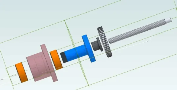
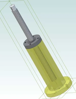
Then I did some research and found the probe screen for the AXIS interface. Seemed nice. Fairly long thread about it on one of the EMC forums. So I ordered the versaPR probe which arrived on Wednesday. Good quality. I ordered and received two extra probes in case I break them.

Got it wired in and just had to try it out.
Touch Probe Test.

Very cool.
 

jcdammeyer

John
Premium Member
Do you have a link to the discussion thread?
Here's the start of it (all 52 pages)
You can see how the suggested changes were incorporated over the length of the thread from 2015.
This is the original
and this is the one that I'm using since I've installed LinuxCNC 2.8 on both the PC and on the Pi4
 

kevin.decelles

Jack of all trades -- Master of none
Premium Member
When you break it down..... what the extent of the configuration in LinuxCNC? Some HAL setup I suspect?
 

jcdammeyer

John
Premium Member
When you break it down..... what the extent of the configuration in LinuxCNC? Some HAL setup I suspect?
The tutorial for the Probe Screen is pretty good. You use git to bring in the zip. Unpack it and put the folders into the appropriate places. There is some editing of the ini and hal files but nothing serious. It's targeted at an automatic tool changer so I found I had to undo some of the changes it suggested with respect to handling Tx M6 G43 commands.
For example in my .ini file I identified what was done with respect to the probe like this:
# begin Touch Probe EMBED_TAB_NAME=PSNG EMBED_TAB_COMMAND=gladevcp -c probe -x {XID} -u psng/python -H psng/psng.hal psng/psng.glade # end Touch Probe # begin Touch Probe [PROBE_SCREEN] # Offset from [AXIS_Z]MAX_LIMIT for performing moves during various probe # screen movements. This must be a negative number. Z_SAFE_TRAVEL_OFFSET = -0.1 [TOOLSENSOR] # Absolute coordinates of the toolsetter pad X = 1.0 Y = 1.0 # Absolute Z start search coordinates Z = 2.0 # Maximum search distance and direction (sign) MAXPROBE = -2.0 # Speed of movements during working in Probe Screen RAPID_SPEED = 60 # Diameter of toolsetter pad TS_DIAMETER = 1.0 # The speed of the reverse rotation of the spindle when measuring the tool diameter REV_ROTATION_SPEED = 300 [CHANGE_POSITION] # Absolute coordinates of the tool change point TOOL_CHANGE_POSITION = 0.5 1 -1 TOOL_CHANGE_QUILL_UP = 1 X = 0.5 Y = 1 Z = -1 # end Touch Probe

Notice the begin/end comments. That's how I kept track of what was there before and what I added for the probe screen. Notice that I also had:
[EMCIO] EMCIO = io CYCLE_TIME = 0.100 TOOL_TABLE = tool.tbl TOOL_CHANGE_POSITION = 0.5 1 -1 TOOL_CHANGE_QUILL_UP = 1

A second set of Tool Change position variables. This caused a double movement of the Z axis for every M6. Commenting one of them out fixed that.

Are you running LinuxCNC?
 

jcdammeyer

John
Premium Member
Here's the box I made to house the Proto board that connects to the 3 spindle sensors and now also the Probe. DB9 to PC supplying 5V, GND and the signals, USB to the Probe supplying the 5V and getting the Open Collector Touch indication. The lid of the box has 4 bumps that fit into 4 holes on the side of the case. No screws required to hold it together.
 

Attachments

  • BoxedInterfaceBoard-1.jpg
    BoxedInterfaceBoard-1.jpg
    38.6 KB · Views: 5

kevin.decelles

Jack of all trades -- Master of none
Premium Member
Great info and great job!

I am running LinuxCNC 2.8, on a very similar machine to yours (G0757/G3617 style). Mine is still pseduo CNC (still using lead-screw and steppers).

Next modification will be to replace vertical motor w/3-phase + VFD.
 

jcdammeyer

John
Premium Member
Mine is also pseudo CNC. I still have the Shumatech DRO-350 working although there Z is on the quill, not the knee while the CNC is on the knee.
I'm glad I did it that way as often the knee has to be moved very close to the lowest limit for items held in the vise or rotary table and a 3/4" chuck in the quill. And I still use the hand operated quill from time to time. I don't like the bevel gears so eventually I'll rebuild the knee to have the motor turn a pulley that turns the ball nut while the screw is held fixed as opposed to the current approach which turns the screw.

I couldn't find a used 2HP 3 phase and new plus cost of VFD moved me to the Bergerda AC Servo. Don't regret it although I will still make new toothed belt pulleys. The one I made for the motor also has a slightly wobble I think so at 3000 RPM it's a bit rough. But that's due to the machinist, not the motor...
 

Attachments

  • BallKneeAssembly.jpg
    BallKneeAssembly.jpg
    30.6 KB · Views: 3
  • AcmeKneeAssembly.jpg
    AcmeKneeAssembly.jpg
    32.1 KB · Views: 2

kevin.decelles

Jack of all trades -- Master of none
Premium Member
I did my Z on the quill for now...... I'm not planning any more mods until I get some hours behind the machine to validate the setup.
 

jcdammeyer

John
Premium Member
I totally get that. My power draw bar has only been 10 years in the works.

I just finished drilling and threading the bottom of the two 1/2" guide rails and some final milling and countersinking on the bottom of the base. I actually used the touch probe a number of times to find the middle of a U shaped area. Yes, I could have done it with the Fowler and Shumatech but it's getting easier to use this probe as I learn the nuances.

Now to wire up the DIN rail with terminals and wire in the solenoids and valves.
 

jcdammeyer

John
Premium Member
Great info and great job!

I am running LinuxCNC 2.8, on a very similar machine to yours (G0757/G3617 style). Mine is still pseduo CNC (still using lead-screw and steppers).

Next modification will be to replace vertical motor w/3-phase + VFD.
Have you posted photos of your conversion anywhere?
 

jcdammeyer

John
Premium Member
Used the probe a bunch of times today. More often than required simply because I'd forget to connect the cable to it. Then start the process and it would fault out with connection made while moving error. I was making a bracket for the draw bar valves and the measurements for the holes and their positions were easier done in metric but my machine is imperial. I'd do a G21 to switch to metric so that all worked but probing expecting to move to find an edge in under 1.0" but have that interpreted as 1.0mm means it moved 1mm and then faulted again.

So I need to fix the macros that do the touch to properly save the G20/G21 state and switch to imperial and do the touch and then go back to metric if it was in metric mode. More about making the bracket in my drawbar thread.
 

jcdammeyer

John
Premium Member
Discovered the issue with the probe not being able to tell me the width of my vise jaws. Or for that matter the ID/OD of a 4" diameter ring.
There's a parameter set in the INI file
# Maximum search distance and direction (sign)
MAXPROBE = -2.0

I think the sign states which direction to probe in first. The assumption is that the distance is the largest you'd go to seek for an edge at worst case regardless of the edge_length parameter which _has_ to be set to the approximate distance from the middle to the edge. I had set this to 2.1"

The result of that is it would find the first edge. Move to it and pause. Then move what should have been 2x edge_length + xy_clearance (0.2") for a total of 4.4" Instead it kept stopping at around 3.5", then went down and either hit the vise jaw or open air depending on what I was probing. In either case a failure. Since the Python code creates this:
G91
G1 X4.4000
G90
and passes that on to the code execution routine it didn't make any sense that it would stop at 3.5. Especially if I used the MDI to move it went to where it was asked.

Well it turns out somewhere inside the python library it checks that and suddenly decides that it's gone too far. Changing the above to MAXPROBE = -3.0 now does not fail. Very odd. 2x edge_length (4.2") isn't considered a bad distance yet it fails if MACPROBE is -2.0. I've reported that issue and I'm digging further into the code to find out where it's broken. But now I can find the center of both small and large holes. Yahoo.
 
Top