• Scam Alert. Members are reminded to NOT send money to buy anything. Don't buy things remote and have it shipped - go get it yourself, pay in person, and take your equipment with you. Scammers have burned people on this forum. Urgency, secrecy, excuses, selling for friend, newish members, FUD, are RED FLAGS. A video conference call is not adequate assurance. Face to face interactions are required. Please report suspicions to the forum admins. Stay Safe - anyone can get scammed.

Pm research #1 steam engine build

PeterT

Ultra Member
Premium Member
PM is USA based so IMP sizing. They also use IMP pipe threads here & there from what I've heard (no first hand knowledge or affiliation, friend of mine has built some kits).

Yes Stuart is from UK.

Depending on one's current state of tooling & financial means, even some of them who live close by suppliers are getting grumpy about the cost & availability of BA type fasteners/tooling & have opted for metric equivalents. But depending on the model, especially steam related, other specialized fittings may also be required & may only be offered with specific threads or sizes.

 

phaxtris

(Ryan)
Premium Member
Premium Member
if the kit came with ba stuff i probably would have considered going to metric, as it is easy to source, and cheap.....but alas the imperial taps were available, not insanely priced and switching over 2 entire kits didnt seem worth the effort


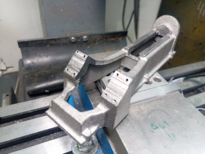
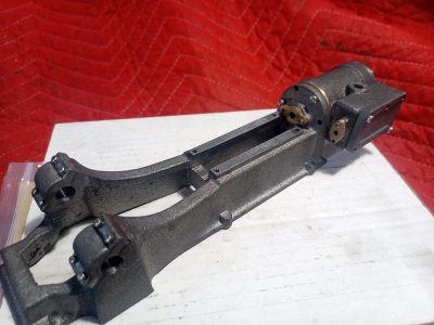
Anyways, with the weather i only had a few hours of actual work to do today and was able to put a bit more time into the steam engine project. The base isnt completed yet, there are quite a few steps to complete it and didnt want to overload one post.....so here it is so far

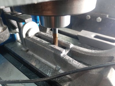
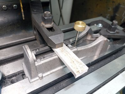
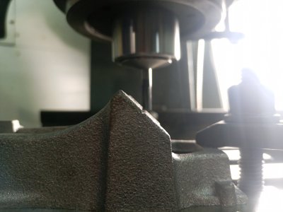
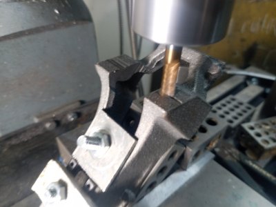
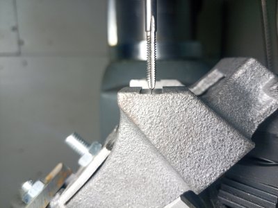
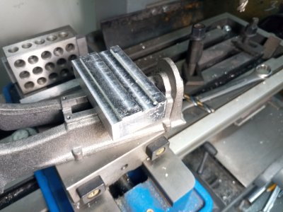
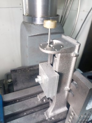
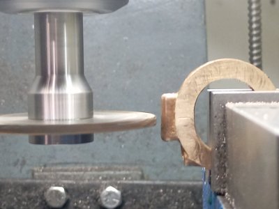
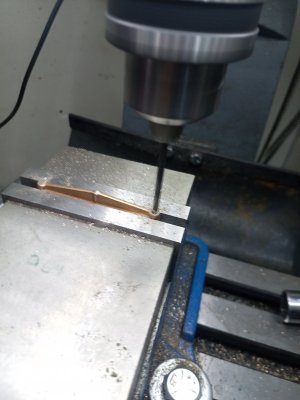
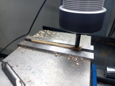
the V grove that you can see milled in the end of the base is to locate the crankshaft CL, the corner of the groove is the CL of the crankshaft. I left a small nail catching line in the casting to help me line everything up when it comes time to drill/ream the casting/main caps for the crankshaft. It was a pretty simple way to locate that feature with the dro. The photo you can see with the tap..that was the only think i had with a precision ground point that i could toss in a collet to get zeroed on the y axis for the holes/step on the cap, i eyeballed that...so im sure its not 100% perfect, but good enough

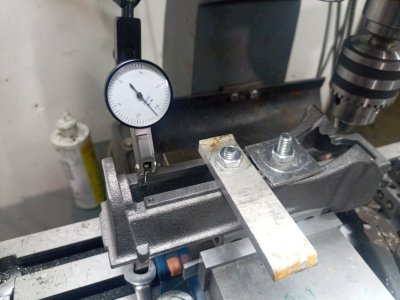
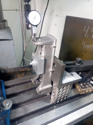
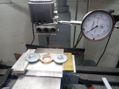
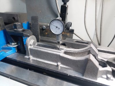
to get the casting in the 45 to mill/drill/etc the main's i copied what blodihacks did, 123 block in the vise, bolt and square up the casting on the 123 block, then set the 123 up at a 45...checked the grove with a small drill bit and an indicator...seemed to be straight, and after milling to the groove i made earlier im confident that it is reasonably square with the other features....yey!

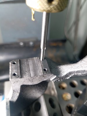
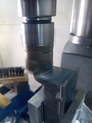
Things still to do.... machine the main caps so that they can be bolted on and the crank bore completed, the cylinder ends needs to be faced and drilled, the packing gland mount needs to be drilled/tapped and at some point i will have to drill the mounting holes so the model can be screwed down to something

IMG_20221220_115835_981.jpg IMG_20221220_121753_261.jpg IMG_20221220_133552_872.jpg IMG_20221220_123803_506.jpg IMG_20221220_144341_082.jpg IMG_20221220_150026_876.jpg IMG_20221220_150815_604.jpg IMG_20221220_154841_732.jpg IMG_20221220_155644_620.jpg
 

phaxtris

(Ryan)
Premium Member
Premium Member
Thanks @DPittman

The cold weather has been a boon for the steam engine project it seems. Some more work completed on the base, the only things outstanding are to drill the oilers for the main caps and the mounting holes

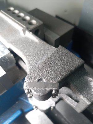
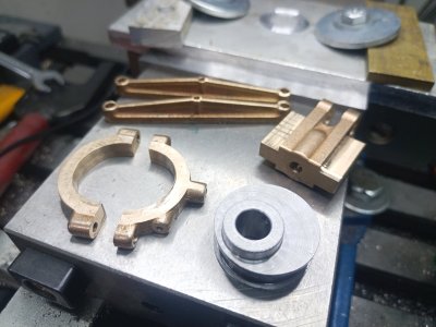
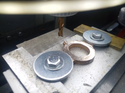
fist thing up was to machine the bearing caps, no pictures here, nothing special, the only thing i did differently than the other two is that i did them while still connected together, cut apart and machined off the sprue once bolted down

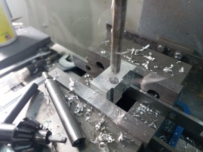
I milled out a small block for use as a jig to facilitate easy setup for the crankshaft boring. it simply indexes on the cross slide and holds the base square, this little block was also turned into the drill guide and then into the last clamping fixture to complete cylinder end machining

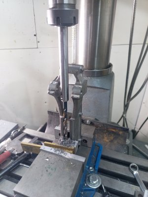
With no surface plate or height gauge I had to drill the hole for the piston rod in the same manner as blondihacks, through a drill guide and with a homemade drill extension...... probably the best one i have made to date. This worked out well enough, and only a few minutes of extra work.

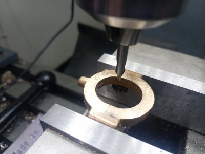
I also had to carry up the small fingernail line for the crank centerline, an olfa knife made a well enough mark. drilled/reamed with no excitement, the hole appears to be centered well on the parting line.....time will tell how easily the crank plops in as to how centered it is

enough blabbing, on to the pictures already...

IMG_20221221_154824_891.jpg IMG_20221221_123410_993.jpg IMG_20221221_124525_329.jpg IMG_20221221_132555_985.jpg IMG_20221221_133608_226.jpg IMG_20221221_142202_890.jpg IMG_20221221_144535_154.jpg IMG_20221221_150052_974.jpg IMG_20221221_153339_591.jpg


phaxtris

(Ryan)
Premium Member
Premium Member
Finally back at it, I've had a bit of a hiatus from this project. Other things got in the way, then a lack of motivation.

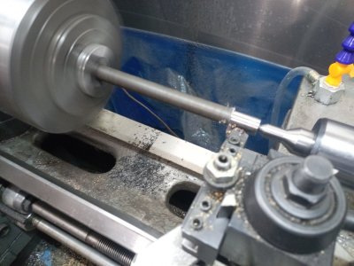
I didn't take many photos of the process this time, I decided I should just concentrate on getting something done to get that momentum going again

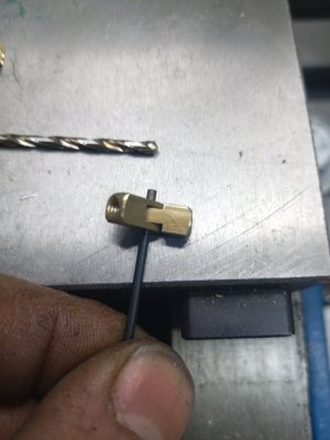
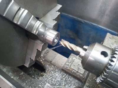
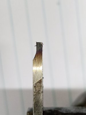
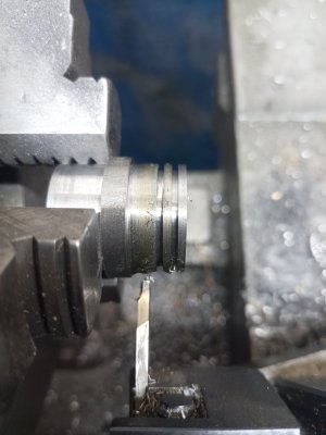
IMG_20230220_122632_450.jpg IMG_20230220_103358_451.jpg IMG_20230220_110147_442.jpg IMG_20230220_111104_804.jpg IMG_20230220_114406_973.jpg IMG_20230219_112935_676.jpg IMG_20230219_110205_083.jpg
 

phaxtris

(Ryan)
Premium Member
Premium Member
Gotta luv it.
If you don't have any packing here is graphite cord from MOEN:


It says 1/8th but it's multi strand so can be made thinner if need be.

pretty sure i have some that came with the casting kit, it came with packing, gasket material and piston rings (teflon), when i get to the more final assembly i will do all those little things, i just wanted to see if it would run ;)
 
Top