• Spring 2024 meetup in Calgary - date Saturday, April 20/2024. discussion Please RSVP Here to confirm and get your invitation and the location details. RSVP NOW so organizers can plan to get sufficient food etc. It's Tomorrow Saturday! you can still RSVP until I stop checking my phone tomorrow More info and agenda
  • We are having email/registration problems again. Diagnosis is underway. New users sorry if you are having trouble getting registered. We are exploring different options to get registered. Contact the forum via another member or on facebook if you're stuck. Update -> we think it is fixed. Let us know if not.
  • Spring meet up in Ontario, April 6/2024. NEW LOCATION See Post #31 Discussion AND THE NEW LOCATION

New member in Edmonton

John Conroy

member
Premium Member
Hi everyone, I am a hobby machinist/metal worker from Edmonton. I've been active in the hobby for many years and in the last 3 years I have gotten more involved and bought a 14 X 40 lathe and a couple of milling machines. The most recent purchase is a 80's vintage "Ferro" brand 10 X 50" mill that I have refurbished. Here are some pics of my machines. Cheers,

John

P8221130_zpsfcnuzxbb.jpg


P9030573_zps3b8ac162.jpg


P8110319_zps23a40613.jpg
 

EricB

Active Member
Whoa, hi new best friend! :p That Ferro is sweet! Welcome to the board. I'm in Edmonton as well and work in a machine shop. Might be able to get you some scrap to work with. Mostly 4140/45 or some different types/sizes of aluminum. I also have a couple of BIG 10" milling vises that I'd be willing to sell cheap if you're interested. I don't have a mill yet and it'll probably be a long time before I can afford a decent sized knee-mill.

Have any photos of some things you've made?
 

John Conroy

member
Premium Member
Thanks guys. Eric. I have done a lot of projects with the lathe and the PM mill, some of which was making new parts for the Ferro mill. The Y axis lead screw and nuts were very worn out when I got it. The lead screw was an odd combination of metric and English sizes, 32mm size shaft cut with a 5tpi thread for .200" per revolution. I re fitted it with some 5tpi 1.25" Acme left hand thread rod to replace the metric size. I bought a 3 foot length of it from the Bolt House for about $40 instead of the $400 it would have cost for a replacement screw in the original metric size. I bought some matching 1.25" left hand threaded nut blanks from Roton industries and machined them to fit like the originals. Here are a few pics of that process.
P4170955_zpsf1zmf6pu.jpg


P4170956_zpskztb2ird.jpg


P4170957_zps0dslo4nv.jpg


P4170958_zpsh4avdrij.jpg


P4170959_zpstv1hdnij.jpg


P4170960_zpsyneyfdex.jpg


P4170962_zpszxnom4vs.jpg


P4170964_zpsabcyibvi.jpg


P4180966_zpszfmbef6i.jpg


P4180970_zps59ivlja3.jpg


P4180974_zpsr3q4v7bu.jpg


P4180975_zpszovnunfo.jpg


P4180976_zps4g4dl5lc.jpg


P4180977_zpsesfwapta.jpg


P4180978_zpscz28abj9.jpg


P4180979_zpsl9p7espe.jpg


P4180979_zpsl9p7espe.jpg


P4180981_zps8akzklx9.jpg


P4180982_zpsiv2ega7j.jpg
 
Last edited:

PeterT

Ultra Member
Premium Member
Welcome John. Nice machines & great pics. I'm always curious about how the 'better' mills accommodate the stationary nut segment that the lead screw engages in terms of minimizing backlash. My King lathe (from memory) is a threaded bronze part with a slit saw cut traversing across the threads. The play is taken up with a fine pitch bolt that tightens & tweaks the thread engagement. I always thought that was a bit crude, but it seems to work reasonably well. (I don't have much to compare to). Did you do anything like this on yours?
 

John Conroy

member
Premium Member
Thanks Peter, there are 2 opposing nuts for each screw and the backlash is adjusted by turning one of the nuts in the housing. The first pic show the nuts, the one on the left is the finished part, the middle one is as it arrived from Roton industries and the right is the original. The second pic shows the nut housing with all 4 nuts for both x and y axis installed.

P4130934_zpszikdq3mc.jpg


P4130938_zpsslpayqix.jpg


P4130940_zps0jsdr5of.jpg


P4130948_zpsq3atsowq.jpg


P4130944_zps45l2y1fm.jpg


P4130945_zpswx2r6avs.jpg


P4130946_zpszxtttaxt.jpg


P4130947_zpsmbt3q5or.jpg
 

John Conroy

member
Premium Member
The Ferro mill did not come with a drive adapter to raise and lower the knee. It is a nine spline drive socket. I made one starting with a short length of 303 stainless round. Here are some pics of the project.

P2090659_zpsa8f6aef5.jpg


P2130670_zps986d4502.jpg


P2130672_zps388bd902.jpg


P2130731_zps846d317c.jpg


P2130733_zpscf342d0b.jpg


P2130735_zps32702a1e.jpg


P2130736_zps64842f6d.jpg


P2130738_zps0acb0d02.jpg


P2140739_zpsf51fb2b3.jpg


P2140740_zpsd391a6c7.jpg
 

John Conroy

member
Premium Member
I needed a socket for the steering head bearing nuts on my Kawasaki Concours 1400. I machined one using a piece of schedule 80 pipe and a short length of hot rolled round stock. Here's some pics.

PB190795_zpsf1eedb9c.jpg


PB190796_zps991cf819.jpg


PB190794_zps3b10441b.jpg


PB190798_zps02d7b77b.jpg


PB190800_zps3d2fc7c0.jpg


PB190802_zpsae788d18.jpg


PB200804_zps9e37e659.jpg


PB200807_zps4f70cec8.jpg


PB200806_zps51b1dfe7.jpg
 

EricB

Active Member
Nice work, John! Looking forward to seeing what else you get up to!

Sent from my B15 using Tapatalk
 

Alexander

Ultra Member
Administrator
You did some really nice work rebuilding that knee mill. Nice to see some real craftsmanship. What are you going to machine next?
 

John Conroy

member
Premium Member
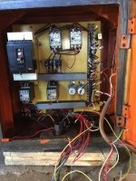
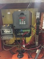
The Ferro mill is 220V 3 phase and my garage is only wired for 240V single phase so I installed a Hyanyang VFD on the mill and I am happy with the results. I have is set up with a remote panel with switches for run, forward/reverse and jog as well as a variable speed potentiometer. I removed the old electrical box from the side of the mill and gutted all the old electrical stuff out of it. I mounted the box on an adjustable pedestal with the vfd and switch panel inside so it can be reached easily. After I got all the settings right I wrote a up a document and drew a schematic in case anyone else wants this information. The switch panel in the picture is temporary. I plan to make something prettier later, I just wanted to get it up and running fast for now.

P2210791_zpsllxnbgpr.jpg


P2210790_zps2mgdnjri.jpg


Huanyang Inverter (VFD)


-Model number HY03D023B

-Input 240 Volt single phase

-Rated output 220 Volt 3 phase 4 HP or 3KW 13 Amps (220 volts X 13 Amps = 2860 watts) (1 HP = 746 Watts) (4 X 746 Watts = 2984 Watts)


Initial Set-Up


-Instructions from vendor (eBay seller “Solar Jean”) suggested the frequency parameters be set in the following order: PD05 set to 60HZ, PD04 set to 60HZ, PD03 set to 60HZ, PD72 to 60HZ. I connected the 200 Volt single phase input power to terminals S and T and the 3 legs of the 3 phase 3 HP motor to terminals U, V, and W. I plugged the VFD in with it temporarily just lying of the table of the mill and it powered up. I set the above parameters as suggested and the Run, Forward and Reverse functions worked from the unit’s built in keypad.


Advanced Set-Up


-I wanted to use a remote mounted control panel to allow remote function of Run, Forward/Reverse, Jog as well as a Potentiometer controlled variable speed. Since the mill has a variable speed head I see no reason to run the motor at more than the rated 60HZ. Using the supplied manual I then made the following switching, wiring and parameter changes to achieve the functions I wanted. I used the schematic on page 37 as a guide for the 3 wire Run, Forward/Reverse switches and the schematic on page 12 for the wiring of the Potentiometer. Page 36 explains how the output terminals can be re-configured for multiple uses. I drew the following schematic after researching the manual. The information on pages 19-26 of the manual details which parameters and settings support the different functions. Since my custom settings are all basic they are all covered on pages 19-20 except PD72 which was part of the initial setup for 60HZ power. These are the connections and parameter changes I made to make the VFD function as I wanted:


See the schematic on the next page, Switch 1 is for D1, Switch 2 is for D2 and Switch 3 is for D3.

-PD01 set to 1 to support use of external input controls.

-PD44 set to 1 to change the function of the “FOR” terminal to D1. When set to 1, D1 is now the Run function.

-PD45 set to 5 to change the function of the “REV” terminal to D2. When set to 5, D2 is now the Forward/Reverse selector. When Switch 2 is open you get forward rotation and when closed you get reverse. See page 37 of the manual for these instructions.

-PD46 set to 6 to change the function of the “RST” terminal to D3. When set to 6, D3 is now the Jog function. It works in forward or reverse depending on the position of switch 2.

-PD02 set to 1 to support the input from the external Potentiometer for speed control.

-PD11 set to 10. This sets the lowest frequency of the variable speed to 10HZ so the potentiometer can adjust the speed of the motor from 10HZ to 60HZ. The factory setting is 0 so when the pot is turned all the way down the motor stops.

-PD14 set to 5 to change the acceleration time (0Hz to 60HZ) to 5 seconds when run is selected. Factory setting is 20 seconds.

-PD15 set to 5 to change ramp down or deceleration time (60HZ to 0HZ) to 5 seconds. I was cautioned to go no lower than 5 seconds without connecting an external braking resistor. The VFD must be given time to dissipate the energy created by the motor as it slows (it acts as a generator when slowing). The internal braking circuits in the VFD cannot support aggressive deceleration and an external braking resistor must be added to slow to a stop quickly. Using the information in the manual, and some internet searches I settled on a 200 ohm, 200 watt resistor. I have ordered but not received it yet so the one show in the schematic is not wired in currently. I will update this information when I get the resistor and experiment with aggressive slow down times.


VFD%20Schematic_zps8fn7xg1w.png


Here is the finished product after I removed the display from the vfd and mounted it on the electrical box door.

P4050900_zpsvoy50p2g.jpg
John
 

EricB

Active Member
Electrical is one thing I know sweet f**k-all about, so I love posts like this. Very impressive.

Sent from my B15 using Tapatalk
 

Tom O

Ultra Member
nice work! I have a 3 phase motor I picked up a couple of months ago so I will have to try something like that.
 
L

Louis Dusablon

Guest
Hi John
I to installed the same VFD on my lathe it works great still have all of the original dashboard function with extra variable speed IMG_1084.JPG IMG_1084.JPG IMG_1284.JPG
 
L

Louis Dusablon

Guest
I was about to buy that same lathe, almost sent the money, then decided to buy the from modern tools
delivered right to my place.
 
Top