Brent H
Ultra Member
@YYCHobbyMachinist : yes indeed - Doctor Diesel is on call 24/7 - have to be in the control room for tie ups and departures in case the fan is hit!
How did you determine that @RobinHood? When a guy buys a new lathe one finds himself in a world of new lingo if you have never been around a lathe before. Like falling out of a two story window and hitting the sidewalk runni
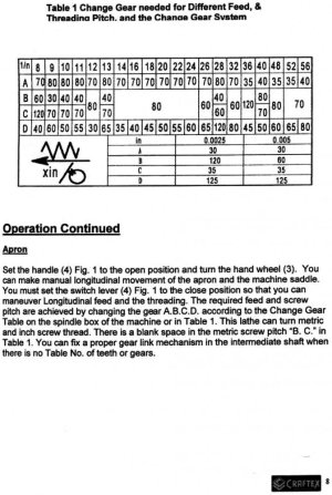
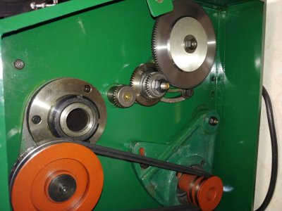
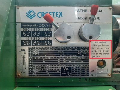
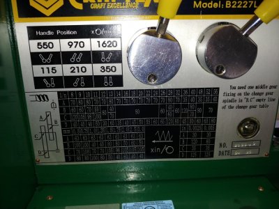
So looking at the gearing photo and going from left to right without taking it apart it should be gear #30, then large gear #60 inner, small gear #35 outer, and the larger bottom gear #125. That is the way I received the lathe gearing from factory.
It would appear my lead screw is designed for both imperial and metric, am I correct in thinking that?
Hey Shawn. Hi from Ancaster. I used to live in T-Bay. Flew for Bearskin Airlines are you PA or KW side? Lots of good scrap finds over at Mission Island for your furnace. As for the threading, I have an old Atlas 10F and it was easier than I thought. To be honest, you’ve tapped into probably the greatest group of folks possible. All great, very helpful and really good guys and gals. I would suggest that you check out threading on YouTube. There are MANY examples but if you check out mrpete222 “Tubalcain” he is likely your best start. His early stuff, where he teaches is amazing, his recent stuff, not so much. Keep in touch, and good luck. Let us know if you need anything, most of us have extra or can find bits and pieces for you...... like a “web of pals” so to speak. We’re all in this together.
Cheers,
Derek
Sent from my iPad using Tapatalk
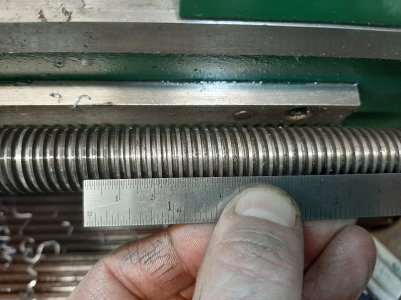
@Dusty : Put a scale on the lead screw and count the threads over 1" - typical lead screw at 8 TPI will be pretty easy to see as the threads will all line up at the 1/8" markings. If it is a metric pitch it will typically have a very odd number of threads within that inch and things will not line up at the 1 inch mark.
Bravo @RobinHood : that is great to find out - read that linked thread - Wow @Dusty - that is some crazy leadscrew but hopefully the new info it will help with threading on your lathe. The lead screw diameter must have been some out of whack engineering cheat to make something fit? 0.7915 is more than 20mm and less than 51/64's ....wow. No wonder confusion abounds!
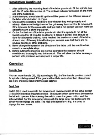
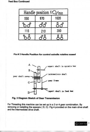
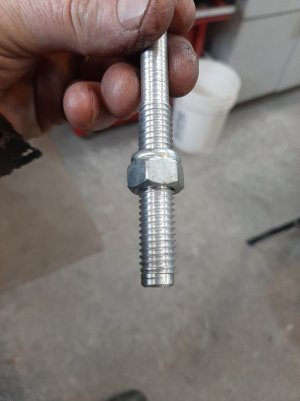
Well,...I had great success today! Not as I expected but once I accepted that I must keep the carriage engaged, I found the process actually easier and less stressful than staring at the wheel, waiting for it to come around and trying to snag it at the exact moment! Here is the lead screw with a ruler so all can see what I have and compare to Dusty's description. Also, completed working threads! I cut the half inch first, then turned it down and cut 7/16 but only had the lock nut for the video. After cutting a longer thread, I ground out the nylok to use it as a regular nut. Figured it would not be impressive to slowly screw a nylok on versus spinning the nut onto the new thread!
Thank you everyone for all of the advice. As I stated over at ShopFloorTalk, I learned a lot about my lathe in the process, cleaned it up, got more comfortable with how the gears work and changing them and now have a pretty good handle on how to cut threads, although practice is in my future!
Here is the first successful thread test. The nylon is still in the nut so I only ran it till it hit.
 If I did the math right on that, it comes out to 2.988 mm metric pitch so, I think it was mentioned before, a 3 mm pitch. The screw being 20 mm x 3 ? Make sense? but as many times as I have swapped gears in the last three days as I worked through this threading dilemna, time well spent! Back then, I was active on Home Shop Machinist, another great site, and I found an old thread that I was part of. Check out post #11 and on.
 @Dusty A few years back, I was on a kick to get more comfortable with changing the gears out. We are all different in what bugs us (pet pieve) but one of the things that bugged me was the number of different tools needed. 14 and 17 mm (iirc) sockets, phillips driver and 8 mm wrench, after you got into the end panel (6 mm allen key?...don't remember) just to swap gears, so, 5 different tools..... think about different feed rates for different finishes...UUUrrrrrrrrr! Of course, most feeding is by hand...
One great little project was combining those tools, mostly. I made a knurled nut for the panel fastener and then got some surplus sockets and welded up a tee wrench that combined all of the tools. It was a diversion away from actually getting comfortable with swapping gears, maybe,
https://bbs.homeshopmachinist.net/forum/general/70551-common-tool-feed-rate
Cheers,
Shawn