• Scam Alert. Members are reminded to NOT send money to buy anything. Don't buy things remote and have it shipped - go get it yourself, pay in person, and take your equipment with you. Scammers have burned people on this forum. Urgency, secrecy, excuses, selling for friend, newish members, FUD, are RED FLAGS. A video conference call is not adequate assurance. Face to face interactions are required. Please report suspicions to the forum admins. Stay Safe - anyone can get scammed.

Myford ML7 Resurrection - A New Summer Project

I don't have any pictures to share at the moment, but I have largely finished the new cross slide gib. I still need to mill the dimples for the gib screws to register into and mill the 60° relief into the long edge of the gib. I also picked up some 2BA screws which I proceeded to modify into proper gib screws instead of my jerry rigged gib screws (did it matter? No. Am I happier now that it's right? Yes).

After some further investigation, I found that my head stock casting is different from the one that Wolfgang from this thread used. The distance between the bearing cap bolts is narrower than the casting that he had. As such, if I'm going to convert to roller bearings for the spindle I'm going to have to come up with my own modification instead of blindly following his. Too bad.

I'll make a bigger post when I have more progress to report, but at the moment I'm trying to figure out how I'm going to fixture the gib to cut the relief angles into it. The easiest approach is probably some sacrificial bolts and round stock to push it into the dovetail of the cross slide, but we'll see what I come up with.
 
Finished up the gib today. I think I'm going to have to mess with the dimples in the gib. As is, I have it properly tight and moving freely for the most part, but if I move it around enough it will bind and I think that is because the gib is moving relative to the gib screws which wedge it tighter into the dovetail. For now it's good enough though. There's a slightly tight spot in the cross slide at the end of travel, but nothing major or unexpected from a lathe of this age/condition.

IMG_3395.JPG

I don't have pics of much of the roughing out process, but I did eventually turn my reclaimed cast iron into something usably flat. I'm not going to worry too much about scraping or grinding it in or anything. I don't think that this lathe is in the condition where it will matter.
IMG_3396.JPG

Here I was still trying to figure out how I was going to fixture the gib to cut the relief at the top and bottom. I have seen a video or post somewhere of somebody doing this with the cross slide itself as the fixture and that made sense to me.
IMG_3431.JPG

IMG_3432.JPG

This is the setup I ended up using. I've seen people using adjustable parallels for clamping the gib before, but I didn't have one that worked well here, so I made do with some bolts and random spacers.
IMG_3433.JPG

I kept the cuts light (under 0.010") and the milling went fine.
IMG_3434.JPG

IMG_3435.JPG

IMG_3436.JPG

IMG_3437.JPG

Once put back together and adjusted a bit everything moves freely and is tight

With the gib finished, I'm fast approaching the point where I need to make a choice about what I'm doing for spindle bearings. I would still love to do a timkin bearing mod, but I'm not sure if that's going be viable. If it isn't I might try turning my hand to pouring babbit as kevin.decelles suggested. Not something that I've done before, but it could be fun. I have no idea where I would source the metal from though. I would have to do some more research on it. As was mentioned, Keith Rucker has some solid videos on babbit pouring and it doesn't look very hard. My main concern would be in making sure that everything is aligned properly before hand. Although realistically, if I go the Timkin route I'll probably need to realign the headstock anyway.

Anyway, those are just some of my musings on options. Feel free to chime in if you guys have any suggestions. Another thing that I'm wrestling with is whether should I repaint the lathe or not. It would look 100x better repainted, but I _hate_ painting with a burning passion. That's future me's problem though.
 
What is Myford's method for the set screws mated into the gib strip dimples? Are the dimples more like a flat notch so the set screw mates it obliquely?

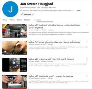
Jan Sverre Haugjord is a Myford restoration fanatic. Looks like he has some specific bearing videos. (I typed babbit in the search box)

1722661102030.webp
 
With the gib finished, I'm fast approaching the point where I need to make a choice about what I'm doing for spindle bearings. I would still love to do a timkin bearing mod, but I'm not sure if that's going be viable. If it isn't I might try turning my hand to pouring babbit as kevin.decelles suggested.

Great project, thanks for posting it.

On the bearing, I would be thinking bronze. Scrape it in after cleaning up (grinding if necessary) the shaft. In some ways (higher loads, can have super low run out) a plane bearing is better than rolling element bearings and you know it will fit. Usually (well, on the machines I've been in) there isn't room to replace plain with rolling element. Where its inferior is top speed (doesn't matter here) and that rolling are so much easier to replace. Bronze, babbit or modified for rolling, you still have to think about alignment, i.e. possibly scraping the HS into alignment with the bed.
 
Last edited:
What is Myford's method for the set screws mated into the gib strip dimples? Are the dimples more like a flat notch so the set screw mates it obliquely?

Jan Sverre Haugjord is a Myford restoration fanatic. Looks like he has some specific bearing videos. (I typed babbit in the search box)

View attachment 50313
I'm sure that's how it is supposed to be. What I did was some shallow dimples with a center drill that I later had to enlarge with a dremel to keep the gib from sliding out when the crossslide moved. My main issue was that I didn't have an end mill small enough to make proper angled flats. I will probably have to tweak them in the end to get the cross slide to move nicely and reliably.

I actually seen several of Jan's videos. Definitely a pleasure to watch and informative. I'll check them out again though and see if there is anything else that I can get out of them.

Great project, thanks for posting it.

On the bearing, I would be thinking bronze. Scrape it in after cleaning up (grinding if necessary) the shaft. In some ways (higher loads, can have super low run out) a plane bearing is better than rolling element bearings and you know it will fit. Usually (well, on the machines I've been in) there isn't room to replace plain with rolling element. Where its inferior is top speed (doesn't matter here) and that rolling are so much easier to replace. Bronze, babbit or modified for rolling, you still have to think about alignment, i.e. possibly scraping the HS into alignment with the bed.

Bronze has occurred to me and would definitely be easier than babbit in terms of availability. I think that I read somewhere that bronze bearings with a non-hardened spindle wasn't the best idea though. Apparently newer Myfords use Bronze plane bearings with a hardened spindle.

Another option (although likely the most expensive one by an order of magnitude) would be to swap to a super 7 head stock as discussed in this thread. The last post makes it sound relatively trivial. Of course that would mean sourcing a whole head stock, which might itself have issues, so I probably wouldn't go this route.

I think that you're right that no matter what option I choose I'm going to have to realign the headstock to the bed. I'm just living in a happy fantasy land where I pretend that isn't going to be a problem ;) .
 
Not something that I've done before, but it could be fun. I have no idea where I would source the metal from though. I


I’ve been watching the Rotometals website. They sell Babbitt in different flavours . I’ve never bought from them though, but pouring Babbitt is a bucket list item for me. My old von wyck lathe has Babbitt and I’ll probably mess with that
 
There are different types of Babbitt depending upon what the speed of the shaft will be.
Tin based and Lead based,
The higher the tin the better it is for higher speeds and loads ( compression strength ). Highest tin ratio is never more then 88-90%
Some times a dash of copper is added to the mix. Depends if its tin or lead based.

We used 90% tin 7.5 antimony and 3.5 copper on the last turbine babbit pour we did.

Great stuff to use as soft faced hammers.
 
Last edited:
My understanding is that all Myford ML7 used babbit bearings. The Myford S7 uses a conical bronze bearing. A number of ML7 users have converted their lathe to use tapered roller bearings. See article by Alan Hearsum in Model Engineer Magazine from 12/2013 and 01/2014. Apologies but I don't appear to have those issues; perhaps another group member can provide them.
 
Bronze has occurred to me and would definitely be easier than babbit in terms of availability. I think that I read somewhere that bronze bearings with a non-hardened spindle wasn't the best idea though.

I think you are right, I didn't realize it wasn't hardened. Seems strange for a spindle shaft, but I guess it works if properly matched with the right bearing material
 
My understanding is that all Myford ML7 used babbit bearings. The Myford S7 uses a conical bronze bearing. A number of ML7 users have converted their lathe to use tapered roller bearings. See article by Alan Hearsum in Model Engineer Magazine from 12/2013 and 01/2014. Apologies but I don't appear to have those issues; perhaps another group member can provide them.
I've heard the MEM conversion mentioned in a couple places, but haven't had tracked the issues down for myself. The "guide" that I'd be following if I go down that route was posed by a gentleman named Wolfgang Huperz to the myford lathes group. It's an interesting read, even if you don't have an ML7 that needs bearings.
 
I think I've decided what I'm going to do about the bearings. I'm going to go with a similar modification to the spindle to the one by Wolfgang in the link I posted earlier (see below).
I actually found a thread where somebody did exactly this after a quick google.
Since I knew that the bearings were previously replaced, I wanted to disassemble the spindle so I could take some real measurements.

IMG_3480.webp

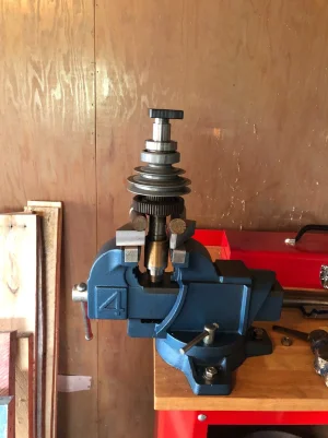
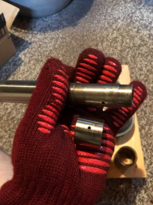
The spindle was pretty stubborn to get apart. I ended up putting it in the oven for about an hour at 350 F then setting it up in the vice as shown above and driving the spindle out from the rest of the parts. The black plate on top was to prevent damaging the back of the spindle with the hammer.
IMG_3481.webp

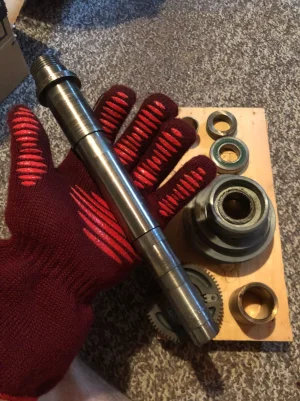
The oven mitt here is because the spindle was still quite hot.
IMG_3482.webp

This sleeve at the rear of the spindle was labelled Torrington and had the part number IR151816. Turns out that it is the inner race for a needle bearing. I didn't get the bearing with the lathe, but that seems like a reasonable choice for this application
IMG_3483.webp

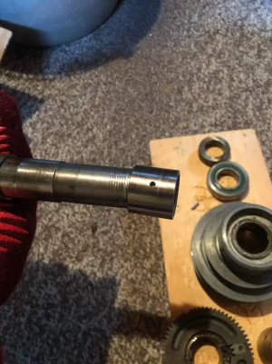
To accommodate the needle bearing, a previous owner turned down the rear section of the spindle from ~1" down to 15/16". This really eats into the threads for the tensioning collar at the rear of the spindle. There is enough there to thread it on, but I definitely don't want to take it down any further.

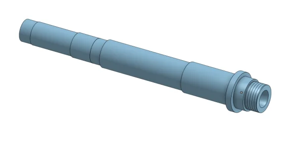
I modelled up the spindle in CAD and started looking around for bearings that would work both with limitations of the spindle and with the limitations of the headstock casting. The two main constraints here are is the gap between the screws for the bearing caps. This rules out the vast majority of bearing options. The next constraint is that the step that the backgear and pulley run on is 1 1/8". Unless I wanted to massively complicate things I cannot go with a bearing with a smaller ID than that. With those two constraints the only combined thrust and radial load non-plain bearing that I could find was the tapered roller bearing that Wolfgang spec'd for his mod (L45449/L45410). The ID is 29 mm and the OD is 1.98".

For the rear bearing I would have loved to once again followed Wolfgang's lead, but with the reduced section on my spindle, his selection will not work for me unless I sleeve that section back up to 1". Looking around, I couldn't find any options for the reduced diameter of 15/16" for the ID of the rear bearing. Resigning myself to the reality of sleeving the spindle, I figured that I might as well use the same bearing for the rear bearing as the front one. As a bonus, L45449/L45410 bearings are only $10 each.

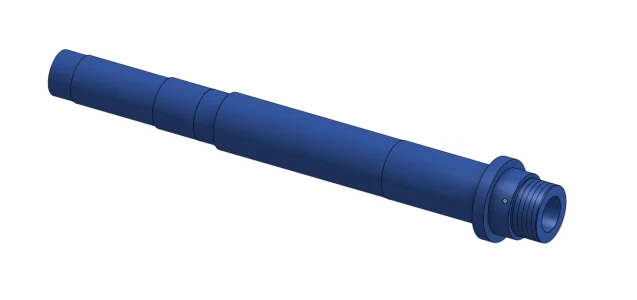
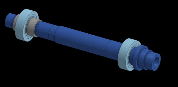
Here are some pics of my plan of attack.

OriginalSpindle.webp

This is the current state of my spindle. It is more or less the same as OEM with the exception of the second last step from the rear, which has been reduced to 15/16" from 1". There is a short section in front of it which is still the original 1" bearing surface.
ModifiedSpindle.webp

This is what I propose to modify my spindle to The only difference is reducing the front bearing's step from ~1.25" down to 29 mm (1.1417"). This is the same modificaiton that Wolfgang made to his spindle.
IMG_3484.webp

Please excuse the black background here, but this is my planned assembly. The grey sleeve's position is approximate so take that with a grain of salt. Also keep in mind that I'm going to need to add at least 4 spacers. to take up the excess spaces where there used to be bearings.

To accommodate the new bearings, I'm going to have to bore out the headstock castings, and find some way to lubricate them. I'm thinking that The spacers on either sides of the bearings could have o-rings on the inner and outer surface to make a sealed-ish reservoir to hold enough oil to keep the bearings lubed.

Let me know what you guys think about this, especially regarding lubrication. I really think that tapered roller bearings are the best option and will end up with the cleanest result in the end. One thing that I don't love is that the sleeve under the rear bearing will have to come off if I want to completely disassemble the spindle. I think I should be able to take it out of the lathe without totally disassembling it, but getting the back gear and pulley off will definitely be a problem.

Anyway that's enough rambling for the time being.
 
Thanks @SightlessSeer for this posting and including all those details. Very interesting and informative. I’m a newbie to having a lathe (Super7) and this thread has given me lots of new info sources to check out (Haugjord, Hearsum, Wolfgang, and more). :-)
 
Back
Top