JohnP
Well-Known Member
For many years I have used a vernier caliper, with the end of the fixed jaw ground to a point, as a marking gauge for laying out dimensions as a sanity check before cutting/drilling/milling, and it has worked very well.
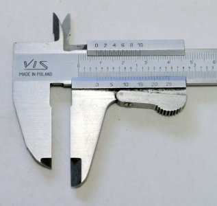
But it had one drawback in that the point dulls fairly rapidly, in spite of the fact that the caliper is labeled as “hardened”. This has resulted in the fixed jaw getting progressively shorter due to repeated sharpening. I thought of adding a carbide tip to the caliper but, then how do you maintain the calibration without a lot of hassle?
My solution was to start from scratch with a new caliper and make a new fixed jaw. Here is the patient.
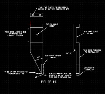
This is a the drawing of the new jaw. There are limited dimensions on it as it was made to fit the caliper I used.
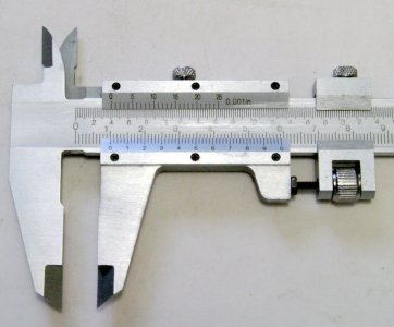
First step was to disassemble the subject caliper by removing the end stop, movable jaw, and depth rod. I also removed, from the moveable jaw, the vernier scales, locking screw and fine adjustment unit. This allowed the bits to be held more securely while being modified.
The movable jaw was modified by cutting off the inside measuring ear and part of the body on the left end, back to the edge of the vernier scale mountings.
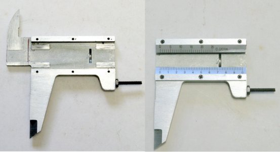
The bar was modified by cutting off its inside measuring ear and the fixed jaw, both back to just slightly wider than the width of the bar.
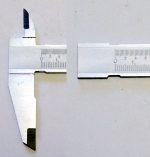
To cut the bits off I used a cutoff disk on the angle grinder as I wasn’t sure how hard the material would be. I then cleaned up the cut edges with a carbide end mill. The movable jaw was then reassembled to the bar, without the depth measuring rod as I had other ways of measuring depth and figured it would just get in the way.
The next job was to make a new fixed jaw. For this I used a length of ¼ by ¾ inch mild steel. First operation was to hold it in the milling vice and mill a recess across the width at the end, the same depth as the thickness of the caliper bar to fit the newly modified bar. In my case .140 deep by .700 wide, leaving a .125” wide section on the end the full ¼ inch thick. This section will be drilled and tapped later for two 2-56 gib (for lack of a better name) screws.
The length of stock was then clamped, upside down, to my angle iron sub table held in the mill vice to mill the thickness of the lower portion of the embryo jaw down to the same thickness of the movable jaw, .140” in my case.
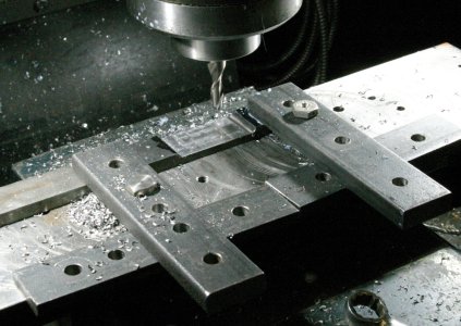
I find the use of this sub table held in the mill vice very convenient for small items that would normally be clamped down to the mill table for machining, as it saves removing the vice and then re-installing it and clocking it parallel to the table again.
The edge that would be next to the movable jaw was skimmed in the mill to just clean up and the recess for the carbide insert milled. The piece of carbide I used was a nominal 3/32”T x 3/16”W x ½”L. As I wanted the insert to be .025” proud of the face of the jaw and extend .094” beyond the jaw material, I milled the recess .070” deep by 5/8” long. The recess was positioned so that when the insert was in position the overall length of the jaw and insert would be .25” shorter than the movable jaw when on the bar. The embryo jaw was then cut off the parent bar and the cut end milled back to make it .344” shorter than the movable jaw. This would allow the insert, when silver soldered in, to be ground back at 45 degrees to make the scriber point, and not cut into the jaw material. The other edge was milled off to make it the same width as the end of the bar that extended out beyond the movable jaw when set to zero.
The new jaw was set vertically in the mill vice and drilled and tapped 2-56, centered on the recess for the bar and .125” in from each end. These screws would then, when tightened, hole the new jaw at 90 deg to the bar.
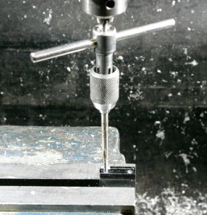
The back side was now hack sawn and milled to the profile shown in the drawing, following the dotted line at the bottom. The section outlined by the dotted line was left on at this stage to facilitate wrapping some wire around the insert and the jaw to hold it in position while silver soldering it on. After silver soldering the carbide insert on and cleaning it up, the back side of the jaw was then milled back to the solid line profile in the drawing. Using the bench grinder the bulk of the excess carbide insert that was over hanging the sides of the new jaw were ground off by hand and the end was ground to a 45 degree angle by eye. The jaw was then clamped to the sub table and the sides of the insert were trued up and ground back to the thickness of the jaw with the diamond cup wheel from my Quorn.
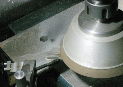
After clamping at 45 degrees in the vice, the end of the insert was cleaned up and ground to a sharp point.
A hole was drilled in the middle of the recess for the bar tapping size for a 5-40 screw to clamp the new jaw securely to the bar. The movable jaw was set to zero on the bar and locked, the new jaw was installed on the end of the bar, and pushed up to the movable jaw and clamped in position using the 2-56 screws. The tapping hole was then used to align the drill to drill through the bar.
Before taking it apart, the bar and jaw were clamped in the mill vice and, using a dial gauge on the edge of the bar, the knee was run up and down and the bar adjusted till it was vertical.
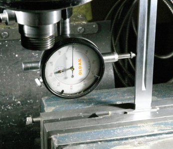
The face of the carbide insert was then lightly dressed with the diamond wheel to true it up at 90 degrees to the bar.
After taking it all apart, the bar was mounted in the mill vice and the hole opened up using a 1/8” carbide end mill then elongated .020” either way to allow some adjustment of the fixed jaw to zero it, and the hole in the new jaw was tapped
5-40.
A 1/2 inch diameter thick washer was turned up to spread the clamping force from the 5-40 screw over a larger area to make for a more secure fixing.
After re-assembling all the bits and pieces, the new jaw was set to zero by slacking off the clamp screw and the gib screws, setting the movable jaw to zero, then nipping up the gib screws just tight enough to take out any slack but allowing the jaw to move. Using the thumb and fingers, the bottom of the new jaw was pressed hard against the movable jaw and the two gib screws tightened along with the clamp screw. The movable jaw was then moved back and re-set against the fixed jaw and the reading noted. If not zero, the procedure was repeated until it was.
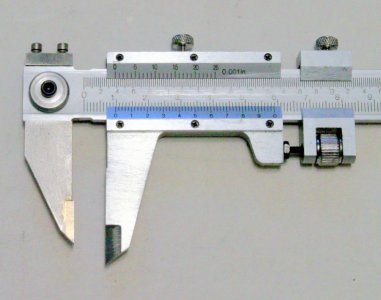
Here is the complete modified caliper
John
But it had one drawback in that the point dulls fairly rapidly, in spite of the fact that the caliper is labeled as “hardened”. This has resulted in the fixed jaw getting progressively shorter due to repeated sharpening. I thought of adding a carbide tip to the caliper but, then how do you maintain the calibration without a lot of hassle?
My solution was to start from scratch with a new caliper and make a new fixed jaw. Here is the patient.
This is a the drawing of the new jaw. There are limited dimensions on it as it was made to fit the caliper I used.
First step was to disassemble the subject caliper by removing the end stop, movable jaw, and depth rod. I also removed, from the moveable jaw, the vernier scales, locking screw and fine adjustment unit. This allowed the bits to be held more securely while being modified.
The movable jaw was modified by cutting off the inside measuring ear and part of the body on the left end, back to the edge of the vernier scale mountings.
The bar was modified by cutting off its inside measuring ear and the fixed jaw, both back to just slightly wider than the width of the bar.
To cut the bits off I used a cutoff disk on the angle grinder as I wasn’t sure how hard the material would be. I then cleaned up the cut edges with a carbide end mill. The movable jaw was then reassembled to the bar, without the depth measuring rod as I had other ways of measuring depth and figured it would just get in the way.
The next job was to make a new fixed jaw. For this I used a length of ¼ by ¾ inch mild steel. First operation was to hold it in the milling vice and mill a recess across the width at the end, the same depth as the thickness of the caliper bar to fit the newly modified bar. In my case .140 deep by .700 wide, leaving a .125” wide section on the end the full ¼ inch thick. This section will be drilled and tapped later for two 2-56 gib (for lack of a better name) screws.
The length of stock was then clamped, upside down, to my angle iron sub table held in the mill vice to mill the thickness of the lower portion of the embryo jaw down to the same thickness of the movable jaw, .140” in my case.
I find the use of this sub table held in the mill vice very convenient for small items that would normally be clamped down to the mill table for machining, as it saves removing the vice and then re-installing it and clocking it parallel to the table again.
The edge that would be next to the movable jaw was skimmed in the mill to just clean up and the recess for the carbide insert milled. The piece of carbide I used was a nominal 3/32”T x 3/16”W x ½”L. As I wanted the insert to be .025” proud of the face of the jaw and extend .094” beyond the jaw material, I milled the recess .070” deep by 5/8” long. The recess was positioned so that when the insert was in position the overall length of the jaw and insert would be .25” shorter than the movable jaw when on the bar. The embryo jaw was then cut off the parent bar and the cut end milled back to make it .344” shorter than the movable jaw. This would allow the insert, when silver soldered in, to be ground back at 45 degrees to make the scriber point, and not cut into the jaw material. The other edge was milled off to make it the same width as the end of the bar that extended out beyond the movable jaw when set to zero.
The new jaw was set vertically in the mill vice and drilled and tapped 2-56, centered on the recess for the bar and .125” in from each end. These screws would then, when tightened, hole the new jaw at 90 deg to the bar.
The back side was now hack sawn and milled to the profile shown in the drawing, following the dotted line at the bottom. The section outlined by the dotted line was left on at this stage to facilitate wrapping some wire around the insert and the jaw to hold it in position while silver soldering it on. After silver soldering the carbide insert on and cleaning it up, the back side of the jaw was then milled back to the solid line profile in the drawing. Using the bench grinder the bulk of the excess carbide insert that was over hanging the sides of the new jaw were ground off by hand and the end was ground to a 45 degree angle by eye. The jaw was then clamped to the sub table and the sides of the insert were trued up and ground back to the thickness of the jaw with the diamond cup wheel from my Quorn.
After clamping at 45 degrees in the vice, the end of the insert was cleaned up and ground to a sharp point.
A hole was drilled in the middle of the recess for the bar tapping size for a 5-40 screw to clamp the new jaw securely to the bar. The movable jaw was set to zero on the bar and locked, the new jaw was installed on the end of the bar, and pushed up to the movable jaw and clamped in position using the 2-56 screws. The tapping hole was then used to align the drill to drill through the bar.
Before taking it apart, the bar and jaw were clamped in the mill vice and, using a dial gauge on the edge of the bar, the knee was run up and down and the bar adjusted till it was vertical.
The face of the carbide insert was then lightly dressed with the diamond wheel to true it up at 90 degrees to the bar.
After taking it all apart, the bar was mounted in the mill vice and the hole opened up using a 1/8” carbide end mill then elongated .020” either way to allow some adjustment of the fixed jaw to zero it, and the hole in the new jaw was tapped
5-40.
A 1/2 inch diameter thick washer was turned up to spread the clamping force from the 5-40 screw over a larger area to make for a more secure fixing.
After re-assembling all the bits and pieces, the new jaw was set to zero by slacking off the clamp screw and the gib screws, setting the movable jaw to zero, then nipping up the gib screws just tight enough to take out any slack but allowing the jaw to move. Using the thumb and fingers, the bottom of the new jaw was pressed hard against the movable jaw and the two gib screws tightened along with the clamp screw. The movable jaw was then moved back and re-set against the fixed jaw and the reading noted. If not zero, the procedure was repeated until it was.
Here is the complete modified caliper
John