Tool Modifications to my bead roller and shrinker/stretcher.

Tool

Bruce Rossiter

Active Member
Hopefully I can work my way through this post. I purchased my bead roller from Princess Auto and immediately realized that it needed a few modifications.
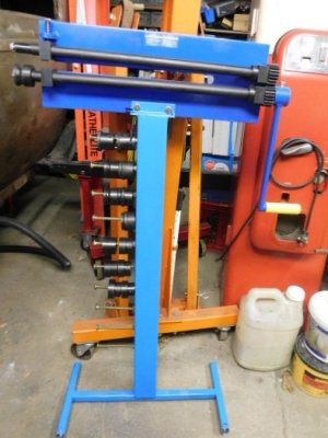
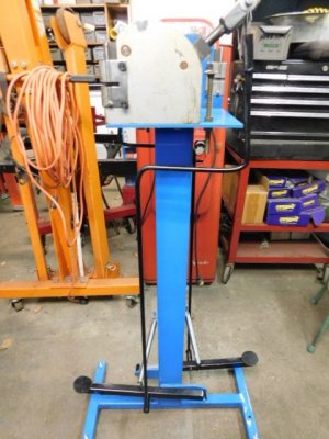
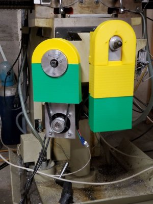
The first change needed was to build a stand to hold the bead roller and all the dies.
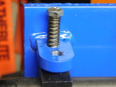
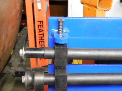
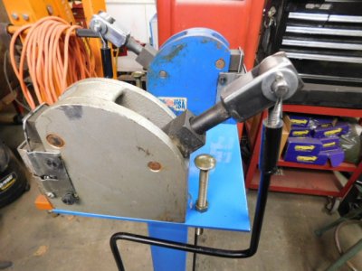
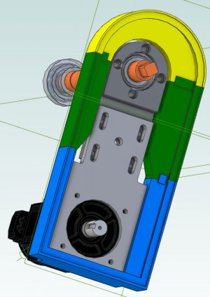
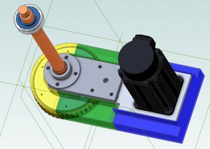
The second change was to drill and tap the bracket and upper bearing support in order to spring load the upper support and shaft. This will return the upper shaft when the depth adjustment is released.
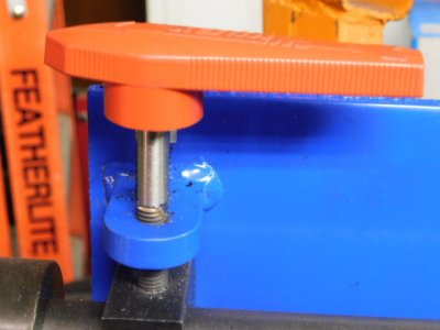
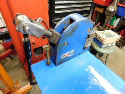
The third change was to replace the tension bolt with a handle (red) eliminating the use of a wrench. It just made it more convenient and quicker to adjust the tension.
The fourth change was to reinforce the back of the main frame to stop the flexing when pressure is applied. The reinforcement was made with 1 1/4" square tubing.
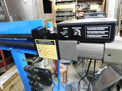
Finally I added a foot operated drive motor to enable me to use 2 hands to guide the metal through the bead roller.
I guess you could say that this was an exercise in changing a cheap bead roller into a useful piece of equipment.
 

Attachments

  • Bead roller 1.JPG
    Bead roller 1.JPG
    95.7 KB · Views: 15
  • Bead roller 2.JPG
    Bead roller 2.JPG
    116.5 KB · Views: 12
  • Bead roller 3.JPG
    Bead roller 3.JPG
    125.7 KB · Views: 11
  • Bead roller 4.JPG
    Bead roller 4.JPG
    118.8 KB · Views: 15
  • Bead roller 5.JPG
    Bead roller 5.JPG
    138.1 KB · Views: 15

Bruce Rossiter

Active Member
The next little project in this thread is the modifications to my shrinker/stretcher. On their own they are somewhat awkward to use. They have to be secured to a workbench and a short handle placed in them to operate them.
The first modification was to build a stand to bolt both units securely. The next modification was to remove the necessity of using a short handle enabling me to use 2 hands to guide the metal. A mechanism was built to link the control lever to a foot operated mechanism. The following pictures show the design of the foot operated mechanism. A stop bolt was installed to prevent excess force being applied.
 

Attachments

  • shrink stand 1.JPG
    shrink stand 1.JPG
    70 KB · Views: 8
  • shrink stand 2.JPG
    shrink stand 2.JPG
    141.5 KB · Views: 8
  • shrink stand 3.JPG
    shrink stand 3.JPG
    141.8 KB · Views: 8

Bruce Rossiter

Active Member
What motor did you use for the bead roller and where did you get it?
The drive system was ordered from Eastwood and it's a well built unit with variable speed and foot control. I received an email offering free delivery and I thought that was a good deal. It turned out the free delivery was only for the US. Needless to say, the cost of the unit, the delivery charge, and the exchange rate all went through the roof. All in all I'm very happy with the drive system.
 

Doggggboy

Ultra Member
The next little project in this thread is the modifications to my shrinker/stretcher. On their own they are somewhat awkward to use. They have to be secured to a workbench and a short handle placed in them to operate them.
The first modification was to build a stand to bolt both units securely. The next modification was to remove the necessity of using a short handle enabling me to use 2 hands to guide the metal. A mechanism was built to link the control lever to a foot operated mechanism. The following pictures show the design of the foot operated mechanism. A stop bolt was installed to prevent excess force being applied.
And the vertical shaft with the S bend in it is stiff enough to not simply flex when pressure is applied to the foot peddle?
I mean, obviously it is, but what size rod is that?
 

Bruce Rossiter

Active Member
And the vertical shaft with the S bend in it is stiff enough to not simply flex when pressure is applied to the foot peddle?
I mean, obviously it is, but what size rod is that?
The rod diameter is 3/8". It's hard to put excess pressure on the 3/8 rod because there's a stop bolt at the shrinker/stretcher and the foot pedal is set to stop when it reaches the lower limit. During it's travel there really isn't much pressure on the linkage as most of the metal is only 18 gauge.
 

jcdammeyer

John
Premium Member
Hopefully I can work my way through this post. I purchased my bead roller from Princess Auto and immediately realized that it needed a few modifications.
Mine is still in the box. Don't remember if it was from PA or KMS when they were only in Vancouver and not on the island here. Please post more about your changes. I'm taking detailed notes. One day I'd like to take it out of the box.
 

Bruce Rossiter

Active Member
Was it specifically for this bead roller or a general purpose drive?

Ah. Found it. https://www.eastwood.com/eastwood-bead-roller-drive-system.html
Most of these cheap bead rollers are similar and the dies are interchangeable. If I recall the mounting bolts needed some modifictions and I think I had to go to Home Depot for different mounting bolts. Eastwood's lower priced bead roller is almost identical to the Princess Auto unit and the harbor freight unit from the US is similar. I'll bet it's the same Chinese company manufacturing them. I'm tied up for most of tomorrow but I can get more pictures of the support I welded on the back side. These units will flex all over the place if they aren't reinforced. Let me know if you need further information on the modifications I made.
 

jcdammeyer

John
Premium Member
You've opened up another wormhole here. While my wife was watching the recorded married at first sight I was watching a whole bunch of bead roller videos. Some interesting modifications. Really would be nice to have an English wheel and the shrinker/stretcher too. But... at the risk of hijacking this thread...

Now that I have a 3D printer, bought after the bead roller, the disire I had to do things like this in metal just aren't there as much. Originally I build the Gingery Sheet metal roller but sold that to a friend along with the power hacksaw. I now have one of those 3 in 1 brake, shear and roller. As yet, haven't even used the roller. Have used the shear and brake a lot.
 

Attachments

  • KneePulleyCover-4.jpg
    KneePulleyCover-4.jpg
    62.3 KB · Views: 3
  • KneePulleyCover-2.jpg
    KneePulleyCover-2.jpg
    71.4 KB · Views: 3
  • KneePulleyCover-1.jpg
    KneePulleyCover-1.jpg
    119.4 KB · Views: 3
Last edited:

Bruce Rossiter

Active Member
You've opened up another wormhole here. While my wife was watching the recorded married at first sight I was watching a whole bunch of bead roller videos. Some interesting modifications. Really would be nice to have an English wheel and the shrinker/stretcher too. But... at the risk of hijacking this thread...

Now that I have a 3D printer, bought after the bead roller, the disire I had to do things like this in metal just aren't there as much. Originally I build the Gingery Sheet metal roller but sold that to a friend along with the power hacksaw. I now have one of those 3 in 1 brake, shear and roller. As yet, haven't even used the roller. Have used the shear and brake a lot.
Your 3D printer does a nice job on the covers and they look sturdier than the covers that are original.
 

jcdammeyer

John
Premium Member
Your 3D printer does a nice job on the covers and they look sturdier than the covers that are original.
They have their issues too. Part of which is "incomplete". When I changed from the DC Servos to smaller AC servo's I grabbed a piece of plate to make the new motor mount. Never did mill it to the correct width so now the Y axis bottom part doesn't fit.

Haven't covered the X axis yet so it gets a bit dirty. This was the DC Servo on the X axis.
X-Axis_EncoderCap.jpg
You can see it's pretty long and I used the 3D printer again to make a cover for the encoder on the back. Bright yellow so I don't run into it. This was also the motor that the DRO tattled on showing it was losing steps. What was interesting is with the exact same HP_UHU driver and current settings it didn't get warm while the Y axis did. And the Y axis didn't lose steps. A resistance measurement showed the motor coils were different.

So I replaced them both with AC servos which are much smaller. And now I'm thinking when I change to ball screws I'll turn it 180 degrees and mount it so its top surfaced is just below the table and in front. Then it won't stick out the LH side as much. But for now I do have a bent metal cover that will screw to the casting and shield the pulley. But it's not done yet either.

XYZ_Motors.jpg
 

Bruce Rossiter

Active Member
They have their issues too. Part of which is "incomplete". When I changed from the DC Servos to smaller AC servo's I grabbed a piece of plate to make the new motor mount. Never did mill it to the correct width so now the Y axis bottom part doesn't fit.

Haven't covered the X axis yet so it gets a bit dirty. This was the DC Servo on the X axis.
View attachment 26005
You can see it's pretty long and I used the 3D printer again to make a cover for the encoder on the back. Bright yellow so I don't run into it. This was also the motor that the DRO tattled on showing it was losing steps. What was interesting is with the exact same HP_UHU driver and current settings it didn't get warm while the Y axis did. And the Y axis didn't lose steps. A resistance measurement showed the motor coils were different.

So I replaced them both with AC servos which are much smaller. And now I'm thinking when I change to ball screws I'll turn it 180 degrees and mount it so its top surfaced is just below the table and in front. Then it won't stick out the LH side as much. But for now I do have a bent metal cover that will screw to the casting and shield the pulley. But it's not done yet either.

View attachment 26006
There sure is some good looking machine work happening.
 

jcdammeyer

John
Premium Member
There sure is some good looking machine work happening.
Thanks. You know the saying. "When all you have is a hammer everything starts to look like a nail".
In my case having a foundry means casting scrap into soft gummy aluminum rather than buying machinable metals. And since I was woodworking way before I was metalworking I enjoy making patterns.
In fact it seems the people who don't like the 'art' of making patterns tend to drift away from casting.
 

DPittman

Ultra Member
Premium Member
The drive system was ordered from Eastwood and it's a well built unit with variable speed and foot control. I received an email offering free delivery and I thought that was a good deal. It turned out the free delivery was only for the US. Needless to say, the cost of the unit, the delivery charge, and the exchange rate all went through the roof. All in all I'm very happy with the drive system.
Do you know what rpm range the motor drives the roller at? I've wanted to add a motor to my PA beadroller also sometime but I can't justify the price of a commercial unit so I get the fun of comming up with my own cobbled together piece. I know I need the ability to go as slow as possible but what is the top rpm range. I'm wondering if a treadmill motor would work.
 

Bruce Rossiter

Active Member
Do you know what rpm range the motor drives the roller at? I've wanted to add a motor to my PA beadroller also sometime but I can't justify the price of a commercial unit so I get the fun of comming up with my own cobbled together piece. I know I need the ability to go as slow as possible but what is the top rpm range. I'm wondering if a treadmill motor would work.
I'm not sure what the maximum speed of the motor is but the key to building an electric drive is to run it very slow as you guide the material. This unit that I have goes from zero RPM to ??? and is reversible. The foot control also gives you flexibility to use 2 hands to guide the material for total control. Offhand I would think a treadmill motor would be a good choice. I'm sure they are a DC motor and easy to vary the speed and direction. I have a digital tach but I haven't used in in years. I'll see if I can check the motor speed if the tach works.
 

jcdammeyer

John
Premium Member
Do you know what rpm range the motor drives the roller at? I've wanted to add a motor to my PA beadroller also sometime but I can't justify the price of a commercial unit so I get the fun of comming up with my own cobbled together piece. I know I need the ability to go as slow as possible but what is the top rpm range. I'm wondering if a treadmill motor would work.
If you look closely at the photos at https://www.eastwood.com/eastwood-bead-roller-drive-system.html you will see that there is a reduction drive between the motor and the input shaft coupler. I'm going to guess it's 100:1. A 3000 RPM DC motor down to 300 RPM which is 5 RPS max speed. That's pretty quick for hand turning. Of course max motor speed might only be 1500 to 2000 RPM so that drops it down to max 3 RPS.

Odds are you'd never run the roller that fast so then as long as the speed control allows the motor to keep full torque at lower speeds you'd be find with a treadmill motor.

But the AC line based speed controls for those aren't the best at low speeds. At least the one I have that I've played with. As yet I haven't put an encoder on the back of one and tried the HP_UHU drive on it.

A long time ago I tried building my own motor driver. Finally gave up and bought a solution.
MOTOR1-5.JPG
DSCN1167.JPG
 

Bruce Rossiter

Active Member
Do you know what rpm range the motor drives the roller at? I've wanted to add a motor to my PA beadroller also sometime but I can't justify the price of a commercial unit so I get the fun of comming up with my own cobbled together piece. I know I need the ability to go as slow as possible but what is the top rpm range. I'm wondering if a treadmill motor would work.
I just checked the Eastwood site and they claim the RPM is from 0 to 20 RPM.
 

DPittman

Ultra Member
Premium Member
If you look closely at the photos at https://www.eastwood.com/eastwood-bead-roller-drive-system.html you will see that there is a reduction drive between the motor and the input shaft coupler. I'm going to guess it's 100:1. A 3000 RPM DC motor down to 300 RPM which is 5 RPS max speed. That's pretty quick for hand turning. Of course max motor speed might only be 1500 to 2000 RPM so that drops it down to max 3 RPS.

Odds are you'd never run the roller that fast so then as long as the speed control allows the motor to keep full torque at lower speeds you'd be find with a treadmill motor.

But the AC line based speed controls for those aren't the best at low speeds. At least the one I have that I've played with. As yet I haven't put an encoder on the back of one and tried the HP_UHU drive on it.

A long time ago I tried building my own motor driver. Finally gave up and bought a solution.
View attachment 26086
View attachment 26088
Interesting stuff. What were you building your own controller for? And why did you end buying a solution?
I've got a treadmill motor on hand but I don't know that the controller board can be operated without the treadmill dash panel.
 

Bruce Rossiter

Active Member
If you look closely at the photos at https://www.eastwood.com/eastwood-bead-roller-drive-system.html you will see that there is a reduction drive between the motor and the input shaft coupler. I'm going to guess it's 100:1. A 3000 RPM DC motor down to 300 RPM which is 5 RPS max speed. That's pretty quick for hand turning. Of course max motor speed might only be 1500 to 2000 RPM so that drops it down to max 3 RPS.

Odds are you'd never run the roller that fast so then as long as the speed control allows the motor to keep full torque at lower speeds you'd be find with a treadmill motor.

But the AC line based speed controls for those aren't the best at low speeds. At least the one I have that I've played with. As yet I haven't put an encoder on the back of one and tried the HP_UHU drive on it.

A long time ago I tried building my own motor driver. Finally gave up and bought a solution.
View attachment 26086
View attachment 26088
The reduction is 75:1 and the maximum speed is 20 RPM according to the Eastwood information.
 
Top