I don't have a ton of experience reverse egineering STL files (facet files) back into 'regular' CAD files. STLs are a bunch of adjoining facets so even a direct conversion to a CAD surface file would result in a facet (bumpy) solid vs a smoother, more acurate model made from within CAD. The way some guys use mesh files (similar I assume as 3D scan point clouds) is import them more or less as selective high res background reference. Then develop their own native surfaces within CAD model by picking specific facet verticies at their discretion (ie ignoring 99% of the remaining mesh). This way you end up quite close to the import surface dimensionally but develop your own 'good' surface more or less from base principles. When no mesh file is available, most allow you to import regular JPG images, ideally 3 ortho views. Position them on their appropriate planes, unify scale to target dimension & then you start developing your model using both pics as reference. There are many YouTube videos showing this with impressive results. It is a bit more advanced surface mdelling.
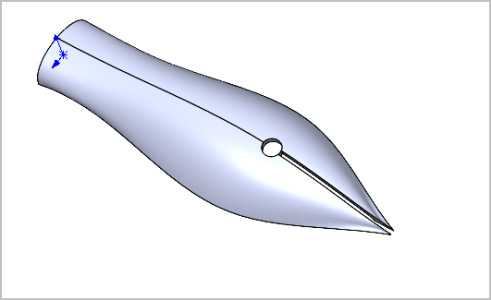
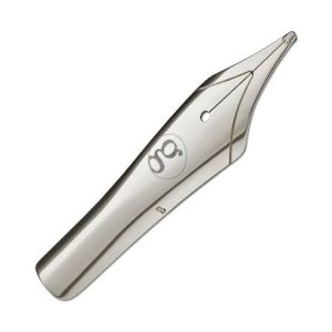
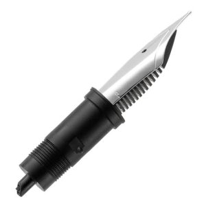
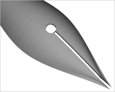
I took a crack at a rudimentary nib just to show some initial workflow to get you going. Real nibs can have some interesting & complex details depending on the type. Surface modelling is a skill unto itself. There are many pathways to get to the end result (highly dependant on the software), but some paths/techniques are better than others.
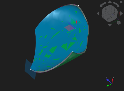
I made a top view of shape because that is a predominant feature. Connect the spline control points to center because these will serve double duty as planes. Mirror the profile to give me eyeball shape. If I had a good top view image it would underly this sketch for better reference
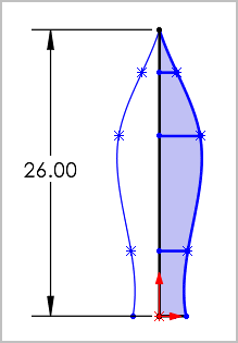
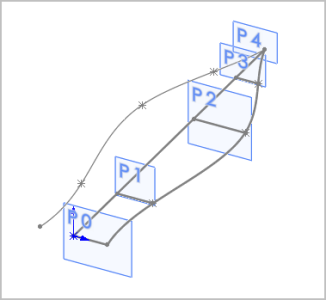
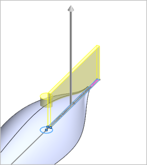
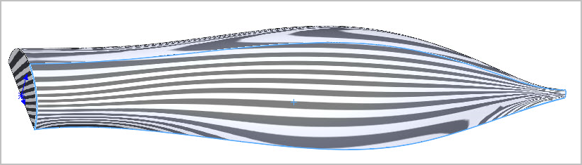
Made a series of cross sections at these planes. Here is where you can excercise control. The curve is a 2-point spline so I can shape it. The X-line segment is converted from reference sketch. The Y segment is whatever I make it. Also I specify the spline is perpendicular to Y-segment. Notice I only work on half the nib, because I intend to mirror. Then the sections are lofted & again you have control options. I use the top view spline as a control curve so the surface will be coincident to it. Then mirror the body about the center plane. Check surface quality with zebra stripes or other curvature tools
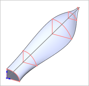
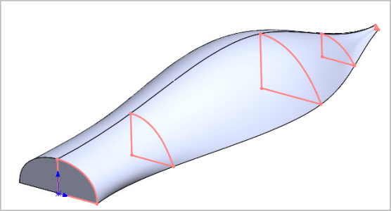
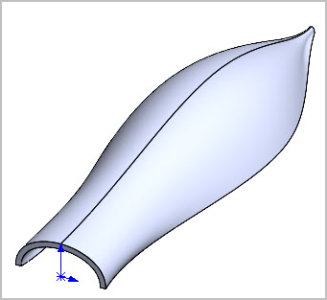
Then I used a shell command. Input wall thickness & removal planes & you get this.
This simple model has a flat bottom just to demo the workflow but when you look at most nibs they are more enclosed on the handle end so you need to reflect these details in the sections. Sometimes adding is easier than subtracting, all depends on the model & where you can best control
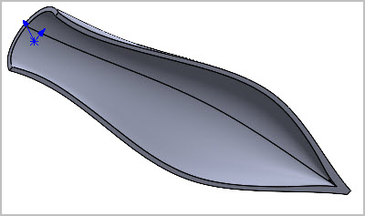
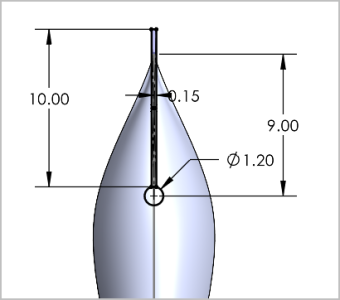
make the slit feature.... and on & on