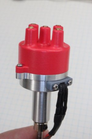
I want my next engine to be spark ignition (vs glow plugs) so I’ve been working on a miniature, scale-ish but functional distributor. This is a 24mm diameter cap for no particular engine. I chose 4-cylinder because that would be the likely minimum, but working towards higher cylinder count on the same body platform. At this point it a bench runner to test different part layouts, materials & methods. I leveraged off of a few other designs developed by people smarter than me.
Electrons & arc jumping don’t scale, so packing the components into a small body is not without its challenges. No spark, no bang. No bang, no joy LOL. That's why I opted for safe but boring glow plugs on my 5-cyl radial. But those have limitations too. Requires methanol-based fuel vs gasoline, relatively high CR, no real ignition timing control. No ability to dwell/advance.
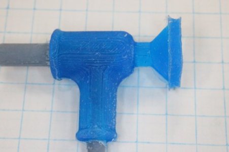
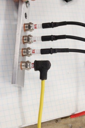
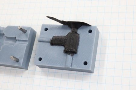
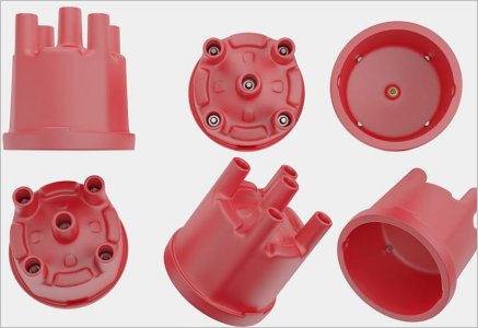
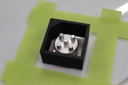
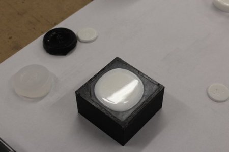
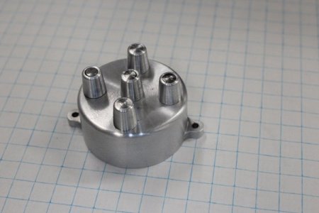
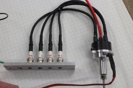
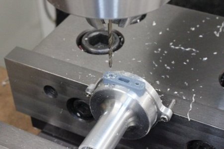
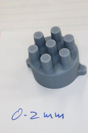
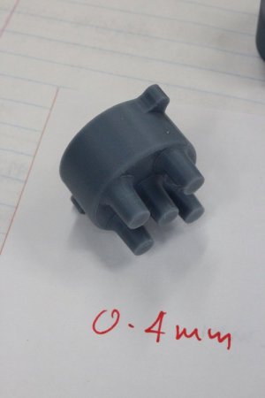
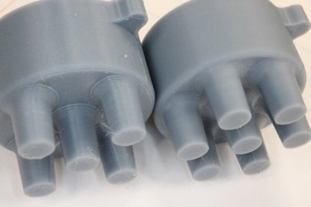
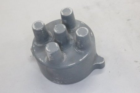
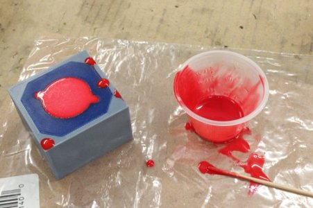
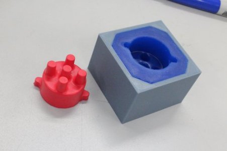
The body is 6061 aluminum, 8mm bearings on either end, spinny parts mounted on a 3mm shaft. Maybe what is a bit unique on my distributor is selective use of 3DP for some parts, which solves some hard to machine issues. FS distributor caps can be quite a funky shape with the main cup, towers layout, fillets, retention lugs or clasps to the body… My cap was 3DP'd from my CAD design. Then some micro-autobody primer work to clean it up & hide the print striations. From this a female mold as poured using silicone confined by 3DP mold plate & dam. Then the cap itself was cast into the silicone using urethane (hard plastic) resin. This was turned in the lathe to hollow out the cavity & lip. The towers were drilled & they hold 2.5mm OD brass tubes which are RC type 2mm banana plugs. My tubes are a little bit sticky-uppy in these pics as I’m still figuring things out. The wires are 16 AWG stranded wire, soldered to the banana plugs.
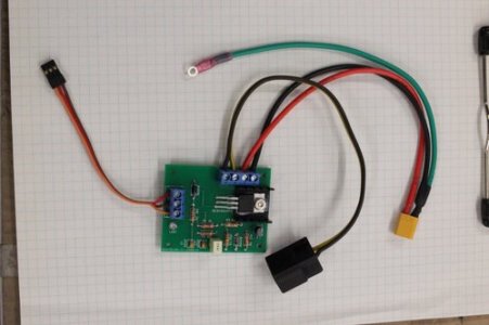
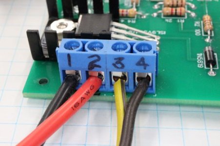
What drives the distributor are dedicated ignition boards or modules, kind of a niche product to model engineering developed by electronics wizards in the hobby. There are not many to choose from but I’m just glad that some dedicated hobbyists figured it out so all I have to do is figure out wiring & color codes. Some modules are capacitive discharge, others use coils. There are pros & cons to each. Shout out to Charlie @CWelkie who made some boards from a circuit published in a ME magazine. I was lucky enough to get one of his inventory spares. It uses a very compact COP (coil over/on plug) so the whole ignition system can be hidden in a compact box. Turns out we travelled in similar RC circles in Calgary when we were young, so that was cool. And Brent @eotrfish you may recognize this particular rotor was made from your PEEK GF-30 slug, thanks!
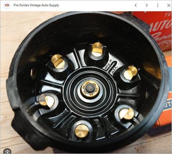
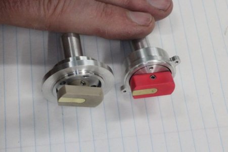
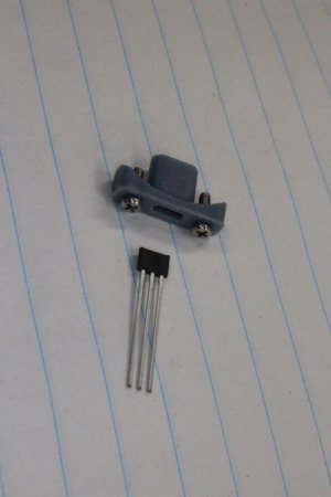
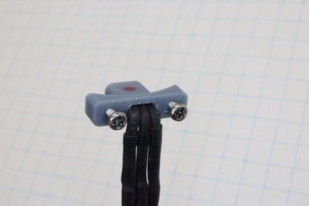
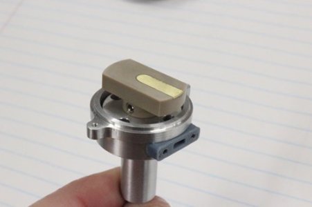
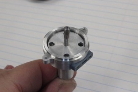
This distributor uses an aluminum magnet wheel: N magnets for N cylinders. A hall effect sensor picks up the magnet pulse & signals the module to fire. I’ve read there are can be practical limits to magnet density before potential issues arise. Another style is a single magnet facing the sensor, but uses a shutter plate between them. The plate has N alternating windows & signal the module that way. And window width correspond to dwell on a coil based system. So less magnets but a bit more finicky construction. I have seen 2 styles of rotors. One with a sprung physical contact on the high-tension terminal. The other is air gap on both HT & cylinder terminal. Again pros & cons to each. I’ve tried both but so far the (0.006”) air gap on both is working.
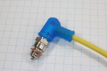
Now that I have sparks (yaaaay!) the plan is to keep refining. I want to increase the terminal count to see if I can get 8 terminals without interference. I’m also working on a shutter plate version. And next step is to make my own spark plugs on smaller thread formats. The commercial plugs are ¼-32 but I have seen them as small as 8-40. Actually ¼-32 match the engines I have in mind so its more of a morbid curiosity thing.
Electrons & arc jumping don’t scale, so packing the components into a small body is not without its challenges. No spark, no bang. No bang, no joy LOL. That's why I opted for safe but boring glow plugs on my 5-cyl radial. But those have limitations too. Requires methanol-based fuel vs gasoline, relatively high CR, no real ignition timing control. No ability to dwell/advance.
The body is 6061 aluminum, 8mm bearings on either end, spinny parts mounted on a 3mm shaft. Maybe what is a bit unique on my distributor is selective use of 3DP for some parts, which solves some hard to machine issues. FS distributor caps can be quite a funky shape with the main cup, towers layout, fillets, retention lugs or clasps to the body… My cap was 3DP'd from my CAD design. Then some micro-autobody primer work to clean it up & hide the print striations. From this a female mold as poured using silicone confined by 3DP mold plate & dam. Then the cap itself was cast into the silicone using urethane (hard plastic) resin. This was turned in the lathe to hollow out the cavity & lip. The towers were drilled & they hold 2.5mm OD brass tubes which are RC type 2mm banana plugs. My tubes are a little bit sticky-uppy in these pics as I’m still figuring things out. The wires are 16 AWG stranded wire, soldered to the banana plugs.
What drives the distributor are dedicated ignition boards or modules, kind of a niche product to model engineering developed by electronics wizards in the hobby. There are not many to choose from but I’m just glad that some dedicated hobbyists figured it out so all I have to do is figure out wiring & color codes. Some modules are capacitive discharge, others use coils. There are pros & cons to each. Shout out to Charlie @CWelkie who made some boards from a circuit published in a ME magazine. I was lucky enough to get one of his inventory spares. It uses a very compact COP (coil over/on plug) so the whole ignition system can be hidden in a compact box. Turns out we travelled in similar RC circles in Calgary when we were young, so that was cool. And Brent @eotrfish you may recognize this particular rotor was made from your PEEK GF-30 slug, thanks!
This distributor uses an aluminum magnet wheel: N magnets for N cylinders. A hall effect sensor picks up the magnet pulse & signals the module to fire. I’ve read there are can be practical limits to magnet density before potential issues arise. Another style is a single magnet facing the sensor, but uses a shutter plate between them. The plate has N alternating windows & signal the module that way. And window width correspond to dwell on a coil based system. So less magnets but a bit more finicky construction. I have seen 2 styles of rotors. One with a sprung physical contact on the high-tension terminal. The other is air gap on both HT & cylinder terminal. Again pros & cons to each. I’ve tried both but so far the (0.006”) air gap on both is working.
Now that I have sparks (yaaaay!) the plan is to keep refining. I want to increase the terminal count to see if I can get 8 terminals without interference. I’m also working on a shutter plate version. And next step is to make my own spark plugs on smaller thread formats. The commercial plugs are ¼-32 but I have seen them as small as 8-40. Actually ¼-32 match the engines I have in mind so its more of a morbid curiosity thing.
Attachments
Last edited:

")