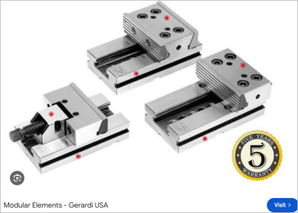
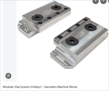
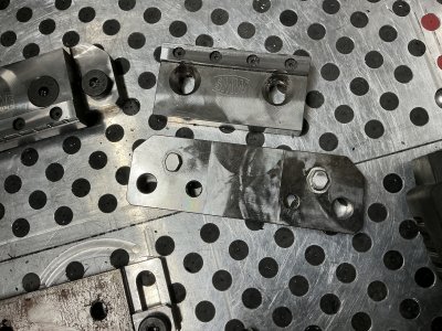
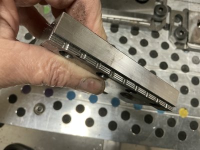
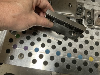
Coincidentally I was looking at some AliExpress mill table clamps that Cliff was mentioning around 3-min mark. And I have to agree with his assessment of them. Ever since the Great T-nut Thread I find myself being a lot more mindful of different table mount do-dads in terms of T-slot loading. I've seen some home shop clamp systems that what I'd call an 'anchored' T-nut, basically a set screw that pokes out the bottom of T-nut to prevent skidding along the T-slot axis under load so that something else can be mounted to another part. Those to me are almost asking for trouble. Usually the anchor screw is finer thread which means more vertical for for given torque & thus putting the cast iron table lip in tension which we know is bad news. But thats another subject.
Despite some rambling on, Cliff did some very interesting real world clamping tests. Before seeing this I was wondering how successful shop made table clamps in this style would be, because the commercial ones are typically hardened & ground (and as shown in video) and seems to me depend on a very good sliding fit between the tounge on movable jaw, however its accomplished. Some have dovetail, his has plain rectangular. some Ive seen something like pin slides. Maybe the rectangular tounge profile could be milled with conventional milling & lapping. I like the idea of setting the work on paralells which now requires thicker jaw, chunkier clamps which is a good thing. Vs the thin nose typically associated with work mounted on the table when you need to mill beyond the edge of work & obviously a protruding clamp is now in the way.
Interesting note in the comment section:
most of the clamps of this type that I have seen use an incline angle of 45º. It's possible to increase the mechanical advantage significantly by using a steeper incline, say 55 or 60º. Thanks for the feedback. My previous version/video was at 60 deg. Actually, I was surprised to see the toe closing lateral forces tending to skid the body away, even at 45 deg, they are already on the high side. I also copy my comment below: "Interesting subject. My last video/design used a front bolt into the table also, but there are downsides. I found with my checks the bolt tension of the front bolt has to be quite low because of the wedging effect, too high and it skids the body away. So really two body bolts are needed to avoid a skidding jaw. " I agree reducing the slot width would help with the guidance ratio, and slightly with crabbing resistance, if there is enough metal to allow this without weakening the structure. Cliff
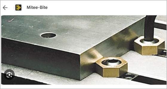
My other idea was basically a cross table bar bolted on multipe T-nuts with a series of Mitee-Bites. This might be better for irregular surfaces, each Mitee-Bite is clamping to wherever the surface happens to be. Withe the elevated work mode (part sitting on parallels) this becomes dead simple. My friend who runs a CNC is not fond of MiteeBites though.
Just curious, what do you guys use?
free PDF plans here

 hallmarkdesign.co.nz
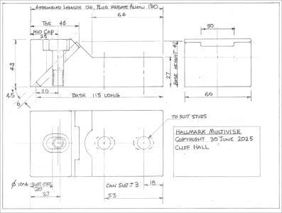
Despite some rambling on, Cliff did some very interesting real world clamping tests. Before seeing this I was wondering how successful shop made table clamps in this style would be, because the commercial ones are typically hardened & ground (and as shown in video) and seems to me depend on a very good sliding fit between the tounge on movable jaw, however its accomplished. Some have dovetail, his has plain rectangular. some Ive seen something like pin slides. Maybe the rectangular tounge profile could be milled with conventional milling & lapping. I like the idea of setting the work on paralells which now requires thicker jaw, chunkier clamps which is a good thing. Vs the thin nose typically associated with work mounted on the table when you need to mill beyond the edge of work & obviously a protruding clamp is now in the way.
Interesting note in the comment section:
most of the clamps of this type that I have seen use an incline angle of 45º. It's possible to increase the mechanical advantage significantly by using a steeper incline, say 55 or 60º. Thanks for the feedback. My previous version/video was at 60 deg. Actually, I was surprised to see the toe closing lateral forces tending to skid the body away, even at 45 deg, they are already on the high side. I also copy my comment below: "Interesting subject. My last video/design used a front bolt into the table also, but there are downsides. I found with my checks the bolt tension of the front bolt has to be quite low because of the wedging effect, too high and it skids the body away. So really two body bolts are needed to avoid a skidding jaw. " I agree reducing the slot width would help with the guidance ratio, and slightly with crabbing resistance, if there is enough metal to allow this without weakening the structure. Cliff
My other idea was basically a cross table bar bolted on multipe T-nuts with a series of Mitee-Bites. This might be better for irregular surfaces, each Mitee-Bite is clamping to wherever the surface happens to be. Withe the elevated work mode (part sitting on parallels) this becomes dead simple. My friend who runs a CNC is not fond of MiteeBites though.
Just curious, what do you guys use?
free PDF plans here
hallmark design
With core skills in tool and die making, tool design, CAD, CAM and CNC, Hallmark Design is focused on quality and function.
hallmarkdesign.co.nz
Last edited: