• Scam Alert. Members are reminded to NOT send money to buy anything. Don't buy things remote and have it shipped - go get it yourself, pay in person, and take your equipment with you. Scammers have burned people on this forum. Urgency, secrecy, excuses, selling for friend, newish members, FUD, are RED FLAGS. A video conference call is not adequate assurance. Face to face interactions are required. Please report suspicions to the forum admins. Stay Safe - anyone can get scammed.

making "spherical" surfaces with a boring head (?)

Yes this is a brain twister to me.

I think it's a lot easier to see if you picture the part spinning at high speed in a lathe chuck, and the cutter rotating about its axis at low speed like a ball turning tool.

The mill situation just reverses the speeds. Otherwise, it's the same thing.

The thing that threw me off is the size of the tool arc. But if the arc diameter is smaller than the part everything is cool and the ball turner works just fine.
 
Yup. I was actually being 'CAD-lazy'. This particular setup can be simulated in CAD with a bit of juggling because A) the cutting geometry = arc sweep of BH is fully defined B) the cut rotation axis = part turning on its axis which in his setup is 45-deg to spindle axis is also fully defined. So CAD will makes 'a cut' in the material just fine & looks good from across the room. Now the trick becomes verifying that the resultant shape is 100% spherical which I think is the objective. There are ways to measure this but that's where one has to be a bit careful. The eccentricity could be there but in the 7th decimal place depending on what collection of dimensions & distances were input. Or sphericity could depends on from what plane perspective. Its one of those things where we can play dumb & let CAD do the heavy lifting. Or alternately sometimes we just know certain things to be true or false based on the rules of geometry: a plane intersecting a cylinder = an ellipse at any angle <> 90-deg,the End. Well, even behind that so called obvious knowledge is probably some convoluted proof theorem sketched out in sand by a guy wearing a robe, but I digress... LOL
 
I might add, mine were done on a horizontal mill
 

Attachments

  • 20230913_191151.jpeg
    20230913_191151.jpeg
    2.9 MB · Views: 9
  • 20230913_185622.jpeg
    20230913_185622.jpeg
    2.7 MB · Views: 10
  • 20230913_184843.jpeg
    20230913_184843.jpeg
    2.7 MB · Views: 10
Why you wouldn't just use a lathe and ball cutter to do this is not clear to me.
well in my case it's because the drivetrain of my lathe has been removed for repair haha. but maybe it's a good way of generating large radii which might be more difficult on a lathe with a ball turner kinda deal


OK so I think this is about it:
asfsdfasfas.jpg

I was gonna re-write it out and whatever but honestly other than the 45° one it's probably easier (and less error prone) to just sketch it out in CAD and let the electric brain do the math...
 
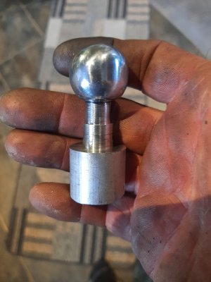
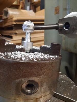
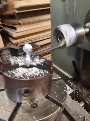
Here is Stefan making a ball on the mill if that helps at all:


Not having used a mill much, and not having all of this equipment, I could not fathom what the heck you guys were talking about. Stefan cleared it up for me. Thanks @thestelster . I do have a ball cutter for my lathe, but it was made for my old lathe and I have not adapted it to the new one yet. Very cool thread. Thank you.

Question...what is the step to take it from a ball on a stick to a perfect ball? I would imagine you do not want any flat surface in such an application but how do you hold it to finish the spot where the stick was? or is that just a bid of hand filing/sanding?
 
Question...what is the step to take it from a ball on a stick to a perfect ball?
Great question. I am not sure either. Maybe similar to making ball bearings. You would need two steel plates with grooves for the ball to pass thru under pressure and rotation?
The ones I made had a flat for a threaded hole, so it didn’t matter.
Martin
 
Back
Top