so I'm trying to repair the Kopp variator in my lathe. basically it's a continuously variable transmission using two drive cones with balls in between them. changing the axis of rotation of the balls changes the ratio between the two drive cones. the variator has worked OK for the whole time I've had the lathe (... 5 years! oh how time do fly), until recently when I did an oil change (to the correct oil!) and now it's incredibly loud. go figure.

variator removed from my Holbrook Minor
I took the variator apart and the balls and drive cones have some smearing on them. a guy on a different forum hardturned the drive cones on his variator, and found that the variator was quite quiet when reassembled.
so I could resurface the cones by hardturning maybe or with a tool post grinder probably; the balls on the other hand I'm not so sure. scotch brite barely does anything and sandpaper affects the finish on the balls, which I would assume to be critical to the operation of the variator. so I had the idea to make a spherical lap and lap them back to round (maybe a bad idea since I've never lapped anything before??)
SO - I've heard of the technique to make spherical surfaces with a boring head and a rotary axis, so I gave it a shot. set the boring head to the ball diameter (70mm), set the dividing head to 45° to allow for tool access (as I thought the proper technique was) and let er rip. but to my surprise the "radius" made is completely wrong:

setup. the FP1 is pretty fun - I had the dividing head tilted the other way and ran out of travel - and then I realized given that the base is offset the correct way would be to move the dividing head to the other side.

looks alright...

hmmmmmm
at first I was sure there must be something wrong with my setup - centering, boring head setting, something. if the boring head isn't dead on center there generated curve would be more like a revolved "w"... but a quick check with the centering microscope shows that if I'm off it's not enough to explain the change in radius. and I checked the boring head setting quickly with a ruler; again it's within the ballpark.
so what's going on? I think the answer is that this technique doesn't actually generate spherical surfaces, but rather elliptical ones. if you can imagine the circle projected onto a plane 45° offset from the spindle axis, the shape it traces isn't a circle anymore when viewed from the work plane:

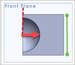
quick solidworks thinkonometry...

template check: it's the correct radius in this plane...

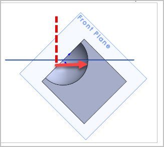
...but in the plane that actually matters
and since the shape is not actually circular there's no radius correction factor or the like to get the right diameter. and the greater the angle is between the cutter plane and the axis of work rotation, the greater the ellipticity (is that a word) will be. and this should hold true for convex shapes made with this technique also.
am I correct in saying the above? I thought lenses were ground with a similar technique to this, and aren't lenses spherical (not talking about intential aspheres here)?

"curve generator" via brittanica.com
and therefore if I want to use a boring head to generate a spherical surface then the tool plane and workpiece axis of rotation need to be parallel (i.e. spindle and dividing head at right angles to each other)?
I,m having a real "low brain" day today so some thoughts would be appreciated...
variator removed from my Holbrook Minor
I took the variator apart and the balls and drive cones have some smearing on them. a guy on a different forum hardturned the drive cones on his variator, and found that the variator was quite quiet when reassembled.
so I could resurface the cones by hardturning maybe or with a tool post grinder probably; the balls on the other hand I'm not so sure. scotch brite barely does anything and sandpaper affects the finish on the balls, which I would assume to be critical to the operation of the variator. so I had the idea to make a spherical lap and lap them back to round (maybe a bad idea since I've never lapped anything before??)
SO - I've heard of the technique to make spherical surfaces with a boring head and a rotary axis, so I gave it a shot. set the boring head to the ball diameter (70mm), set the dividing head to 45° to allow for tool access (as I thought the proper technique was) and let er rip. but to my surprise the "radius" made is completely wrong:
setup. the FP1 is pretty fun - I had the dividing head tilted the other way and ran out of travel - and then I realized given that the base is offset the correct way would be to move the dividing head to the other side.
looks alright...
hmmmmmm
at first I was sure there must be something wrong with my setup - centering, boring head setting, something. if the boring head isn't dead on center there generated curve would be more like a revolved "w"... but a quick check with the centering microscope shows that if I'm off it's not enough to explain the change in radius. and I checked the boring head setting quickly with a ruler; again it's within the ballpark.
so what's going on? I think the answer is that this technique doesn't actually generate spherical surfaces, but rather elliptical ones. if you can imagine the circle projected onto a plane 45° offset from the spindle axis, the shape it traces isn't a circle anymore when viewed from the work plane:
quick solidworks thinkonometry...
template check: it's the correct radius in this plane...
...but in the plane that actually matters
and since the shape is not actually circular there's no radius correction factor or the like to get the right diameter. and the greater the angle is between the cutter plane and the axis of work rotation, the greater the ellipticity (is that a word) will be. and this should hold true for convex shapes made with this technique also.
am I correct in saying the above? I thought lenses were ground with a similar technique to this, and aren't lenses spherical (not talking about intential aspheres here)?
"curve generator" via brittanica.com
and therefore if I want to use a boring head to generate a spherical surface then the tool plane and workpiece axis of rotation need to be parallel (i.e. spindle and dividing head at right angles to each other)?
I,m having a real "low brain" day today so some thoughts would be appreciated...


")
 . I've only thought of doing this operation once, to make some balls on the end of rods so I can make some variable fixturing bars for the weld table. Not a high accuracy task though.