• Scam Alert. Members are reminded to NOT send money to buy anything. Don't buy things remote and have it shipped - go get it yourself, pay in person, and take your equipment with you. Scammers have burned people on this forum. Urgency, secrecy, excuses, selling for friend, newish members, FUD, are RED FLAGS. A video conference call is not adequate assurance. Face to face interactions are required. Please report suspicions to the forum admins. Stay Safe - anyone can get scammed.

Machine Make a precision spindle.

Machine

Mcgyver

Ultra Member
This will be long. If it seems long to you, it was a friggin marathon for me. Probably the most difficult thing I've made and now its done! yippy! I'll do this in several posts, more tomorrow.

A decade ago I bought an Aciera F1. Before the deal was concluded I managed detect that the spindle was in serious trouble. No runout, but you could move it several though by applying lateral pressure. At the time I had no idea what the bearing arrangement was, or I probably would have passed. Instead I negotiated a deep discount for the pooched bearings and the machine came home with me.

The bearings at the business end are needle bearings with the shaft being the inner race and the housing being the outer race. Deckel used this on some mills as well. What it accomplishes is a very robust spindle with a relative small diameter. It is also in my opinion, the poorest spindle design of all time ..... bearings are a wear part with a service life and with this structure, instead of just replace a bearing, the whole spindle is basically toast.

What to do. There is a place in Germany that wil`l rebuild it. Thousands of dollars. They regrind the surfaces and make or buy needles of the precise sized needed for the new dimensions. Yuck.

Instead I started designing and found with some creative use of threads and mixing in some imperials bearings with super precision AC's, I could just make a spindle that would accommodate the required OD and collet. With a limited range, the challenge is have all the steps you need along shaft and spindle and still having enough room to fit a bearing.

Forlorn and spindless.....


20191217_095848-1300x975.jpg


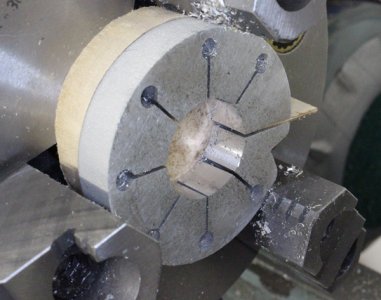
Rouging out the spindle housing

DSC_9485-1300x870.JPG


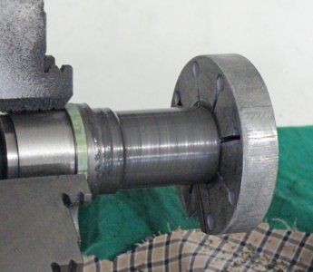
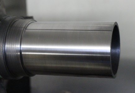
I used preharded 4140 for everything. After roughing, I ground it


DSC_9507-1300x870.JPG


Then some long drilling

DSC_9611-1300x870.JPG

more to come....
 

Mcgyver

Ultra Member
Another instalment. Photos of the original.

The original spindle had a precision needle bearing (not your off the shelf bearing). It rode on a taper collar that is forced up the taper spindle and that is how clearance/preload is set. Similar to a precision roller bearing where you drive the inner race up a taper on the spindle

DSC_5721-1300x870.JPG

The real problem comes from the fact that the outer race is the housing! ##$@%@#$(^#$$


here you can see the spindle with the tapered collar removed

DSC_5956-1300x870.JPG


and the spindle housing interior

DSC_5720-1300x870.JPG

I asked the Bill Huxhold what I should do, the answer was "You've got a problem!"

Sorry I jump around a bit, this goes bad to 2016 and just gather all the shots.


The new housing:

DSC_9446-1300x870.JPG

I never use a centre in the headstock (which technically is always a live centre as it rotates with the work) but prefer to turn a 60 degree cone on any old hunk steel. This insures perfect alignment

DSC_9465-1300x870.JPG
 

Mcgyver

Ultra Member
Except for the exterior dimensions and collet mount, the whole spindle design is new. I could just fit super low profile P4 AC's in the bottom, and went with two deep groove bearings at the top. The original had the needle bearing and two AC's at the top

The fit into the machine tool is so finicky I elected to lap the final OD. The housing passes through the bore shown in the first photo and gets clamp by a bolt that slight distorts the cast iron. The original was pefect to a lot better than a tenth over its length and I wanted the same. With lapping I can creep up on it and concentrate the lapping to tight spots. With fine compound, an area what is a 10th off is readily apparent.


Making a lap (test fitting with the original housing

DSC_9618-1300x870.JPG


DSC_9633-1300x870.JPG

constant checking with an indicating mic until its perfect. The mic is set with a gauge block and essentially used as a snap gauge

DSC_9649-1300x870.JPG

again, a little bit out of sequence, but the fit of the large section is really important. The motor and twp speed gearbox relies on this fit alone, the two are held together just by the fit and two 60 degree pointed screws. The house is a very close sliding fit, it can be taken on and off by hand but is tight enough it would fall out (there is nothing but the fit holding it in place)

20240623_085340-1300x1300.jpg
 

Mcgyver

Ultra Member
ok, now I need to bore the two housing ends, grind for the bearing mount surfaces and thread for the retaining nuts.

I didn't have an internal grinder I was happy with, so started to figure out how to use this Cincinnati grinding spindle. Ages ago I made a big T slotted plate to replace the compound and this made a nice platform to bolt everything to. But it all took time to fashion.


MWZ_8290-1300x866.JPG


It is mission critical to the bores on both ends perfect aligned with the OD of the housing. With a bit of practice and a good indicator, its not difficult to dial work in to better than a tenth. However this is not good enough ..... I guarantee that a few inches away where you got things perfectly concentric a tenth, there will be eccentricity. The work will have a wobble and the spindle shaft/bearings will bind.

To overcome this, you have to indicate it in in two plane. This can be a very tedious process. I've it take hour or have had to walk way in frustration. I wanted to do a video on it but youtube has taken down my channel. Bizzare and frustrating, mine's a sleepy little channel with nothing contentious ..... yet one day I get an email that its been take down "for repeated and severe" infractions to do with spam and misleading, or some such accusation. No warning email, just a note that you're done .... and I haven't the foggiest clue why.


MWZ_8220-1300x866.JPG


MWZ_8270-1300x866.JPG


MWZ_8273-1300x866.JPG


measured with a micron bore gauge checked against a mic set to gauge blocks. . Got to hold your tongue just so!


MWZ_8265-1300x866.JPG
 

Mcgyver

Ultra Member
I'm going to thread from left to right as there are very tight shoulders in there. There is a narrow curved bottom relief groove on this shoulder, and at the end of the ground bearing surface.


MWZ_8351-1300x866.JPG


The blue is magic marker. The gearbox on this lathe has so many controls I always blue the work, engage the leadscrew and, with a scriber held against the tool post, scratch the helix so I can check it with a thread gauge.


MWZ_8316-1300x866.JPG

The nut was made using thread wires and hasn't yet been parted from its parent material


MWZ_8360-1300x866.JPG


thread away until it will smoothly screw in


MWZ_8358-1300x866.JPG


Basically the same process on the other end - here the original nut is being used to test fit the thread. I end up making a nut, but this was an easy, at hand, way to check. Here you see I used a pencil instead of blue and scriber to check the helix, whatever works

DSC_2136 mod-1300x870.jpg


And this is the housing done! Next up, the spindle shaft.
 
Last edited:

PeterT

Ultra Member
Premium Member
Very impressive. Quite the undertaking. Thanks for documenting.

Side question on the aluminum lap. I've done this myself but found the clamp bolt to be very sensitive especially with a new lap charge. Even with fine threads. Subsequently I saw Renzetti's method where he enters the lap bore with band saw, making the clamp slit. But then he makes shallow radial infeed cuts around the ID before backing out the blade. Did you do this? It definitely made the forth & back action a bit smoother somehow, so I'm guessing the compound has a place to go, or maybe its churning & recycling compound a bit within the channel? The other mod I made which I think was probably stolen from a commercial lap is somehow marry a wrench to the clamp screw itself so you can adjust the squeeze on the fly while the machine is still turning vs stop & start.

For my radial liner OD's I made a lap as shown. The idea was to combine the slits with end relief holes so that hopefully? it closes down more radially like a collet principle. In my minds eye I think a single clamp bolt on a split cylinder is basically distorting it something like a clam shell 'C' action if that makes sense. But the question is, does it really matter? I wish I knew someone with ANSYS haha. Laps are consumable items anyways although they can always be re-dressed to be re-used for larger dimensions. My experiment worked but I'm not sure any better than a simple lap.
1719858342749.png
 

Attachments

  • IMG_2563_edited-1.jpg
    IMG_2563_edited-1.jpg
    131.9 KB · Views: 5
  • IMG_2577_edited-1.jpg
    IMG_2577_edited-1.jpg
    132.4 KB · Views: 5
  • IMG_2579_edited-1.jpg
    IMG_2579_edited-1.jpg
    86.1 KB · Views: 4

Mcgyver

Ultra Member
Thanks for encouragement Gents, onto the shaft.

The tolerance for the fits of the P4 AC, especially in low profile is minuscule. That's for the housing and shaft fit, about a tenth or less irrc. Its bloody hard to work to that and these parts end up with a lot of time in them, so I spend a lot of time setting up and pondering.

Anyway, a challenge with the shaft is the long hole for the drawbar. Again working with a heat treat chrome moly steel.

There is a really neat technique for long holes, without gun drill, where you can do 30x the diameter or more and it come out with 1 -2 thou.

I've detailed here and it really works. https://www.metallum.shop/ideas/#deephd

first job is to make long drill bits and reamers, extension are silver soldered on.


DSC_0262-1300x870.JPG


DSC_9819-1300x870.JPG


DSC_0276-1300x870.JPG


I wrote the process out with a diagram so I'd be less likely muck it up - its gets a bit repetitive as you are pulley the (heavy) tailstock back and changing

tooling several times per 1/2 inch


DSC_0279-1300x870.JPG

to give a sense of it, that's a 12" caliper.

DSC_0280-1300x870.JPG
 

Mcgyver

Ultra Member
and finally we the draw bar!


DSC_0283-1300x870.JPG

Next, its OD grinding so I turned centres in each end

DSC_0288-1300x870.JPG


Using the centres, I also turn semi circle profile relief grooves where needed

DSC_0317-1300x870.JPG


DSC_0366-1300x870.JPG


DSC_0356-1300x870.JPG

Lots of different surfaces and all need to be concentric. The grinder is a T&CG with a motorized work head. Very light as cylindrical grinders go, but infinitely better than no way to cylindricaly grind. I scraped this machine from the ground up and everything is to a tenth on alignment, that makes accurate work quite possible. The top table pivots and as you start grinding, with enough allowance, you can dial in the pivoting table you get diameters end to end with less than a tenth deviation .... then you are parallel and then you grind to dimension.
 

Mcgyver

Ultra Member
Measurement is with an indicating mic set to gauge blocks

DSC_0374-1300x870.JPG


Makes a tenth rather large!

After grinding, I set up an V block and the shaft to mill a keyway. A gear slides on the shaft so shift from high to low

DSC_0381-1300x870.JPG


DSC_0400-1300x870.JPG


Work then goes back to the lathe to thread the AC inner race retaining nut.


Added a relief groove


DSC_0405-1300x870.JPG


Then threaded the section. That's an M20 x0.50 thread, I had to make up threads to fit within the available diameters as the shaft steps from the business end bearing diameter down to the outer deep groove bearing dia.


DSC_0413-1300x870.JPG
 

Mcgyver

Ultra Member
Electrical......

220/440 motor.

I wanted a proper contactor turned on with latching on button with no power to the VFD until it was on. Also have some 12V volt fans I wanted to turn when the power was put to the VFD. I used a Vevor box which was quite good. Almost went for the Hammond enclosure when I spotted the Vevor. Cheaper AND it had the removable back plate, I hate enclosures without that lol


20240629_082950-1300x1300.jpg


20240629_115630-1300x1300.jpg


20240630_075254-1300x1300.jpg


20240630_134902-1300x1300.jpg


20240630_112438-1300x1300.jpg
 

Mcgyver

Ultra Member
Very impressive. Quite the undertaking. Thanks for documenting.

Thanks Peter. On the lap, I was aware of the style RR uses. Probably works better, Rob is a smart cookie, just but the way I did it worked fine.

Gorgeous work!
Is that a D bit reamer ? I tried several times but never managed to get it to work properly.

Thanks! Not a D bit, just a boring bar
 
Top