I came across an article in Model Engineer's Workshop issue 281 that showed how the author realigned the head of a round column mill/drill using a laser line level mounted on the head. The laser point pointed at a vertical line drawn on the opposite wall. All he had to do was ensure the laser was on that vertical line after moving the head to maintain alignment.
-
Spring 2024 meetup in Calgary - date Saturday, April 20/2024. discussion Please RSVP Here to confirm and get your invitation and the location details. RSVP NOW so organizers can plan to get sufficient food etc. It's Tomorrow Saturday! you can still RSVP until I stop checking my phone tomorrow More info and agenda
-
We are having email/registration problems again. Diagnosis is underway. New users sorry if you are having trouble getting registered. We are exploring different options to get registered. Contact the forum via another member or on facebook if you're stuck. Update -> we think it is fixed. Let us know if not.
You are using an out of date browser. It may not display this or other websites correctly.
You should upgrade or use an alternative browser.
You should upgrade or use an alternative browser.
Maintaining Round Column Mill/Drill Head Alignment.
- Thread starter johnnielsen
- Start date
Thanks for posting John. I dug issue 281 up and had a read. I have a cabinet opposite my mill that is only 3' away, so I'm not sure this is a reasonable approach for me.
I figure there must be some kind of super accurate reflected beam sensor out there some that would let you project onto the table. What to look for or what they would cost is beyond me.
Craig
I figure there must be some kind of super accurate reflected beam sensor out there some that would let you project onto the table. What to look for or what they would cost is beyond me.
Craig
Last edited:
I've seen that method used in a couple of videos. Seems like it would work well enough.
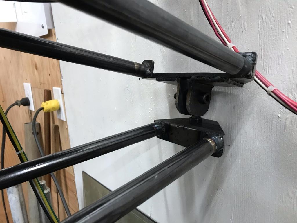
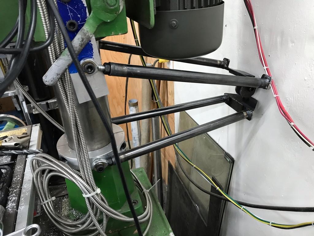
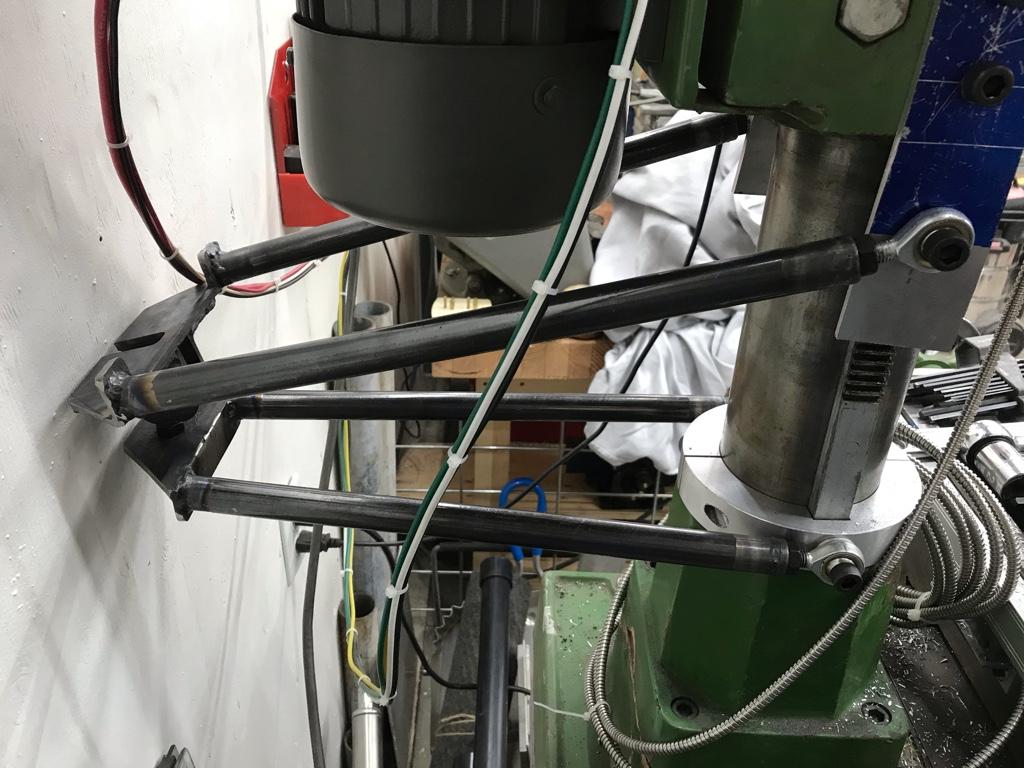
I built a set of arms, that function like paralevers. Using ball joints one set of arms is connected to a collar on the base, the other set is connected to the head with ball joints. Both sets are hinged together using ball joints.
It looks like it's connected to the wall but it is free floating.
![7693129c92adb0e11c02731c59ce7e05.jpg]()
![be7fc304effb2717532741c3c0f64bdc.jpg]()
![f7722bda3799749954c54497317c498b.jpg]()
I built a set of arms, that function like paralevers. Using ball joints one set of arms is connected to a collar on the base, the other set is connected to the head with ball joints. Both sets are hinged together using ball joints.
It looks like it's connected to the wall but it is free floating.
Last edited:
I've seen those articles too. I'm sure we could do the trig that would calculate accuracy based on the width of laser dot (they can vary) and obviously the further the wall is away, the better it will be. The reference line and machine head travel must be same (plumb makes sense). But what I never understood is canyou see the dot/line from th eother side of the shop? Otherwise you jack the mill up/down, walk over, look at the dot, walk back, tweak it...walk back.... I'm sure someone has also thought of a reflecting mirror to get the feedback visual closer to you. Seems like it would be cheap to try if you had the space.
I've seen those articles too. I'm sure we could do the trig that would calculate accuracy based on the width of laser dot (they can vary) and obviously the further the wall is away, the better it will be. The reference line and machine head travel must be same (plumb makes sense). But what I never understood is canyou see the dot/line from th eother side of the shop? Otherwise you jack the mill up/down, walk over, look at the dot, walk back, tweak it...walk back.... I'm sure someone has also thought of a reflecting mirror to get the feedback visual closer to you. Seems like it would be cheap to try if you had the space.
Devil made me send this.

A laser dot should suffice. I understand they are really bright and some can be adjusted to a pinpoint.
Someone check my grade 7 math. Or maybe its grade 5? Too long to remember & too lazy to look it up LOL!. Might just be simple ratio of 2 triangles.
Just a guesstimate example. If you can improve on the distance or dot/line accuracy the accuracy number gets better.
Still, almost 4 thou isn't what I'd call awesome.

Just a guesstimate example. If you can improve on the distance or dot/line accuracy the accuracy number gets better.
Still, almost 4 thou isn't what I'd call awesome.

This is interesting. What if Craig got some cheap hand mirrors and sent the laser down the wall with a 45 degree mount then bounced it back through the 45 mirror again and back against the wall behind the machine? So instead of 16 feet it was 32?
DaveR8 how well does that paralever solution work?

DaveR8 how well does that paralever solution work?

It works really well.This is interesting. What if Craig got some cheap hand mirrors and sent the laser down the wall with a 45 degree mount then bounced it back through the 45 mirror again and back against the wall behind the machine? So instead of 16 feet it was 32?
DaveR8 how well does that paralever solution work?
View attachment 12092
I spent some time trying to measure how capable this guide is at returning the head to the same location.
My process was this:
Raised the head to a height where quill could be fully extended plus another four inches.
Put a mag base with a thousandth's indicator to the right of the quill.
Extended the quill only as much as necessary to get the stem of the indicator against the quill.
Moved the X-axis till the indicator made contact.
Moved the Y-axis back and forth till I found the high point of the diameter of the quill similar to dialing in a 4-jaw chuck.
Zeroed the dial.
Fully extended the quill.
Locked the X and Y axis.
Raised the head to the maximum height while still making contact with the indicator. While cranking the handle the needle swung about 20 thou but settled back down when I stopped cranking.
Tightened the head bolts
The quill was within 1/2-3/4 of a tick off zero.
Slacked the head bolts and dropped the head to the lowest point possible.
Re-tightened the head bolts with the same result.
I snugged up the jam nuts on all of the ball joints and that reduced the deviation to about a needle's width off zero
I did notice that when cranking the head up (less so down) that the angle iron at the hinge was flexing maybe 1/8"-1/4". I think some additional lateral bracing would stop the flexing and likely any movement while cranking.
That's awesome Dave!
Thanks!
I still need to add the additional bracing I’m very happy with it.
I’d love to take credit for it but it’s not my original idea. I copied a build off of Hobby-Machinist.
Sent from my iPhone using Tapatalk
Wondering if a cheap temporary solution in a bind would be an inexpensive tile layer's laser? That way you would have two reference lines on the wall in front of you? It wouldn't be as accurate as a point laser over a longer distance, but might be a fast and dirty and worth a try.
I don't have a round column mill, so I just put one on my drill press....

I don't have a round column mill, so I just put one on my drill press....

historicalarms
Ultra Member
Forgive my ignorance boys but I fail to see the importance of a complicated apparatus on a round column mill. Ive had my mill for 20 yrs or so and can count on 1/2 one hand how many times minute' accuracy was required after a head rise or lowering...I could pretty much eyeball the head back to center and if it was a bit off or accuracy check was required a simple TPI set-up was used with minute adjustment's made using the x-y travel of the table. There is no "plumb" adjustment available on a round column mill...it will not change no mater where your head is orientated on the column. The head locks to the column and the quill locks to the head in the exact same orientation every time.
If I were to see a need for immediate repeatable accuracy, I think a simple clamping split collar (such as already illustrated in the photo's) and a flat welded to it with a hole drilled in it at exact center from column to quill center. Drill the hole to be nominal to any piece of drill rod or ground rod you have around. Now to use this column collar set-up, you have your work piece & your head set to do the original cut and perform that. now, before you loosen the head for adjustment, you put a piece of the bar in your collet or chuck whichever your using, now loosen the collar ( I can be positioned sideways to the head so it is out of the way when not needed),swing it under the quill and upwards to spud the bar in the hole, now lock the collar to the column. Now you can unlock the head and adjust it up or down within the length of your rod ( any length that fits between workpiece & chuck). The head orientation to the table & column will remain the same as the rod slides up or down in the flat plate...lock the head-unlock the collar, swing out of the road-remove rod from chuck done.
I very much might be wrong but it seems far more fool proof and easier to use than a hayrack of flexible arms& legs or laser lights that are only accurate to the size of the spot (again a I say I can come that close just by eyeballing head alignment.
Even a more simple method would be a witness mark on the locking collar and one on the bottom casting of the head...again lining up two witness marks will be well within the accuracy of any mill drill given all the sliding clearances required for them to function easily and be built inexpensively.
Methinks it's also driven by the desire many of us have here to tinker and make things better—or at least to try a different method.Forgive my ignorance boys but I fail to see the importance ...
")
but but but lasers ...
I could bounce the beam around the basement enough times to obtain a mile. Would that provide sufficient resolution?