• Scam Alert. Members are reminded to NOT send money to buy anything. Don't buy things remote and have it shipped - go get it yourself, pay in person, and take your equipment with you. Scammers have burned people on this forum. Urgency, secrecy, excuses, selling for friend, newish members, FUD, are RED FLAGS. A video conference call is not adequate assurance. Face to face interactions are required. Please report suspicions to the forum admins. Stay Safe - anyone can get scammed.

Lathe Wiring

Blue Wall

Active Member
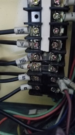
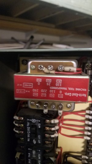
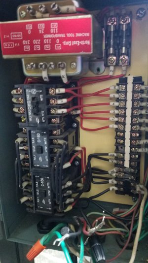
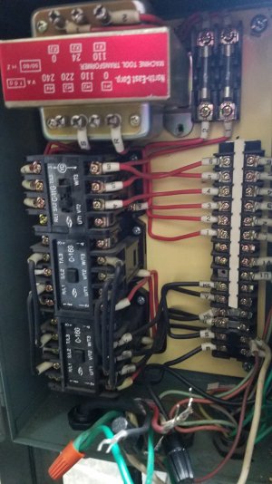
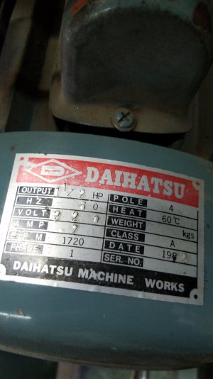
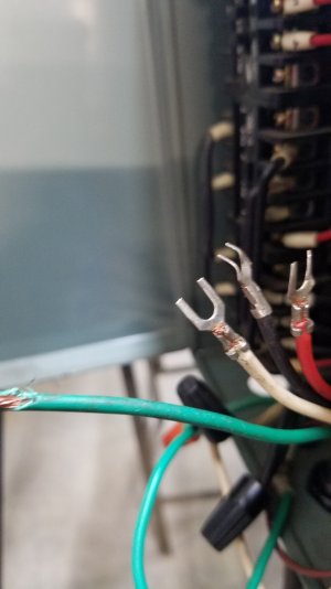
Hello All: I bought a King Canada 1440B lathe. Nice unit. There are some issues I am ironing out! One is wiring in the motor. It is a single phase 1.5 hp 220volt photo (1). The input is 110 and I believe there is a transformer(4). Because it is 220 motor there are three wires plus a ground (2) The 110 input hooks to the bottom 2 of the electrical strip opposite s/r(3). There are four open connections on the right above the the input labelled across from U/M6/V/M5 (3) My question is where do the red/black/white wires hook into the open connections. I know where the ground goes. I hope this is clear. I have basic wiring and believe I know where they go but!!! I don't want to chance making a mistake and frying something that is no longer available. Pictures 5&6 are just extra for reference. Thanks for your time! Ron
 

Attachments

  • 20231128_142513.jpg
    20231128_142513.jpg
    255.4 KB · Views: 44
  • 20231128_142445.jpg
    20231128_142445.jpg
    199.8 KB · Views: 48
  • 20231128_142454.jpg
    20231128_142454.jpg
    240.2 KB · Views: 41
  • 20231110_155418.jpg
    20231110_155418.jpg
    224.6 KB · Views: 45
  • 20231125_172553.jpg
    20231125_172553.jpg
    309 KB · Views: 38
  • 20231125_172553.jpg
    20231125_172553.jpg
    309 KB · Views: 43
Have you contacted King Canada? They seem to be pretty good about responding.
 
From these pictures, it looks like you have 4 wires coming into the box. Normally, black and red are hot, white is neutral and green for ground. That would provide 208 / 220 / 240 (red to black) or 120 (red to white or black to white) plus ground.

its hard to tell from the picture, but the transformer looks like it is wired to step down 220V input to 110V output. Tracing the 1 & 2 and R & S wire pairs should make this more clear. But that seems odd since your 4 wire input provides that voltage directly

tracing the M5, M6 and U, V wires will help too. But since there is arc damage between M6 an U, they must both have been connected to something. My _guess_ is that U & V are red and black with white connected to M6. but it could easily be the other way around
The damage you noted wasn't arc damage. The motor bracket broke and pulled the wires out braking the plastic on the strip. There is 120 volts at the m6 connection. There is only three wire input, the four wires I showed were for the motor...thanks for helping!
 
I'm thinking it is 220 single phase in. That transform looks way is too small for the motor and is for auxiliary stuff (maybe coolant, lamp, 110 plug ....just a guess, not looking at the lathe).

Where was it before and how was it hooked up?

Best case is obtaining an electrical schematic. Second best is to start sketching one - can't entirely see in that jumble what is connected to what

They put the service manual online, but no electrical drawing! Nothing on the inside of the panel cover?
 
My apologies to the OP. @Mcgyver has more guts than I do. I was (and, still am) very reluctant to comment on this thread. Too many things don't make sense, and I am always reluctant to give electrical advice to someone who is not electrically inclined.

BUT, I note that Mcgyver didn't provide specific wiring advice but did try to help anyway. He is a smart cookie and I agree with his comments 100%. That's been my guess from the first post.

Just as an aside, in all my life I have never seen a machine that has a high hp motor wired for 220 with 110 in to the unit and a transformer in between.

I have seen lots of dual voltage motors that can be wired for 220 or 110.

I have also seen 220 in with a neutral and split output to a motor wired for 110.

I have seen lots and lots of 110 in with a 110 motor and lots and lots of 220 in with a 220 motor.

But NEVER 110 in with a motor wired for 220. NEVER.

A few guesses:

A Hill Billy might have used 110 Wire connected to 220 at both ends with no neutral. Wire is wire. If you ignore conventions and codes, it will work just fine.

Another guess is that you bought the lathe from a guy who wired it wrong, it never did work, and that's why he sold it.

IMHO, you either have to find the wiring diagram for it or make your own. Other faster easier approaches might have a lot of appeal, but I don't think shortcuts are a good idea. The odds of magic smoke appearing in the works are simply too high.
 
NEVER 110 in with a motor wired for 220. NEVER.

A few guesses:

A Hill Billy might have used 110 Wire connected to 220 at both ends with no neutral. Wire is wire. If you ignore conventions and codes, it will work just fine.
I agree. Just to flesh out what I believe Squatch is saying, a guess is that the former owner installed a 240 V line from the electrical panel to near this machine. But then didn't put in the proper 240 V NEMA receptacle (6-15). Lazy hacks will just use a regular 120 V (5-15) as it provides the same number of electrical connections. Often there will be some smudgy sharpie marks that say '220' on the receptacle side.

On the machine, they'll then swap the plug for a 120 version and all will be 'OK' as long as _only_ that machine is ever plugged into that receptacle. In fact, _usually_ if someone plugs a 240 V machine into a real 120 V receptacle, nothing too bad will happen. (YMMV!!!) Typically, the machine will either not run at all or will run very weakly. So weak the motor will stall under very light loads. No guarantee, though.

The more common problem is that someone plugs a 120 V device into what appears to be 120 V receptacle. A lot of things really don't like to get double the voltage they're designed for! I'm sure we've all heard of someone taking a hair dryer and plug adapter to Europe. They do provide heat...but only briefly! ;)


HTH,

Craig
 
My apologies to the OP. @Mcgyver has more guts than I do. I was (and, still am) very reluctant to comment on this thread. Too many things don't make sense, and I am always reluctant to give electrical advice to someone who is not electrically inclined.

BUT, I note that Mcgyver didn't provide specific wiring advice but did try to help anyway. He is a smart cookie and I agree with his comments 100%. That's been my
My apologies to the OP. @Mcgyver has more guts than I do. I was (and, still am) very reluctant to comment on this thread. Too many things don't make sense, and I am always reluctant to give electrical advice to someone who is not electrically inclined.

BUT, I note that Mcgyver didn't provide specific wiring advice but did try to help anyway. He is a smart cookie and I agree with his comments 100%. That's been my guess from the first post.

Just as an aside, in all my life I have never seen a machine that has a high hp motor wired for 220 with 110 in to the unit and a transformer in between.

I have seen lots of dual voltage motors that can be wired for 220 or 110.

I have also seen 220 in with a neutral and split output to a motor wired for 110.

I have seen lots and lots of 110 in with a 110 motor and lots and lots of 220 in with a 220 motor.

But NEVER 110 in with a motor wired for 220. NEVER.

A few guesses:

A Hill Billy might have used 110 Wire connected to 220 at both ends with no neutral. Wire is wire. If you ignore conventions and codes, it will work just fine.

Another guess is that you bought the lathe from a guy who wired it wrong, it never did work, and that's why he sold it.

IMHO, you either have to find the wiring diagram for it or make your own. Other faster easier approaches might have a lot of appeal, but I don't think shortcuts are a good idea. The odds of magic smoke appearing in the works are simply too high.
Thanks....the more I think of what you said the more it makes sense. I will continue to my search.
guess from the first post.

Just as an aside, in all my life I have never seen a machine that has a high hp motor wired for 220 with 110 in to the unit and a transformer in between.

I have seen lots of dual voltage motors that can be wired for 220 or 110.

I have also seen 220 in with a neutral and split output to a motor wired for 110.

I have seen lots and lots of 110 in with a 110 motor and lots and lots of 220 in with a 220 motor.

But NEVER 110 in with a motor wired for 220. NEVER.

A few guesses:

A Hill Billy might have used 110 Wire connected to 220 at both ends with no neutral. Wire is wire. If you ignore conventions and codes, it will work just fine.

Another guess is that you bought the lathe from a guy who wired it wrong, it never did work, and that's why he sold it.

IMHO, you either have to find the wiring diagram for it or make your own. Other faster easier approaches might have a lot of appeal, but I don't think shortcuts are a good idea. The odds of magic smoke appearing in the works are simply too high.
I
 
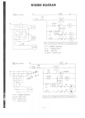
Eureka I found a wiring diagram. The trouble is I don't understand what some of the symbols mean. Thanks again for your help and expertise.
 

Attachments

  • 1440B wiring.jpeg
    1440B wiring.jpeg
    183.7 KB · Views: 19
This diagram may be very incomplete, but it does not look like it matches your pictures. Neither schematic has the same number or labeling scheme as is shown in the pictures.

Looking at the picture more closely, it appears that both the insulating plastic is broken and there was an arc

I don't know. I think I would have to see it in person. There are a whole bunch of other wires and it is not at all clear what goes where
 
The schematic appears to be a 200V single phase circuit that powers a 220V spindle motor and 220V pump. The transformer is necessary in units that can be wired for either 220V or 110V, as in my lathe and a few other machines I have. in those cases the control circuits are either 110V or 24V, and the transformer is necessary.

I have a sneaky suspicion that someone has messed with the wiring because normally the controls would be 220V coils as well for a single voltage motor. Far more straightforward and cheaper, too. Someone has messed with the wiring in this case - for instance, a single voltage motor swapped in for a dual voltage, and the wiring 'made to work'.

Step 1: identify the correct leads for 220V operation of your spindle motor (and that it is, in fact a 220v motor with the correct amperage range as stated on the motor plate. Repeat for the pump motor. This is in the absence of any control wiring or switches on the lathe. (and external on/off switch is highly recommended)

From there you can begin to rewire your lathe. I infer from some of your comments that you aren't comfortable with wiring electrical circuits, is that right? In any event I agree with @mbond: someone with more experience should have a look at your machine.. Where are you located?
Thanks for your clear explanation. I agree with your conclusions. I live in Camrose. Thanks again for taking the time to respond. I live in Camrose.
 
Looking at the wiring diagram there is a reversing switch so there will be extra wires from the motor. Off the top of my head there should be 4 plus the ground.
 
I am new around here and have been amazed (the real meaning of this word) about how much mutual help there is
 
Back
Top