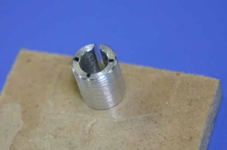
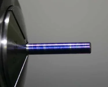
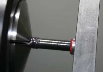
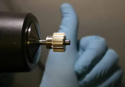
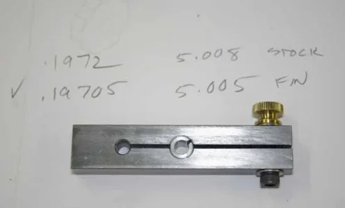
Here is my lapping tool adventure. I had to bring some 5mm (~0.197")O1 drill rod down slightly to an acceptable fit & finish. It will become an axle for the idler gear cluster on the model radial engine. The OD of the lap is 5/16", basically to match a nominal drill size. The smaller hole is a stress relief & springyness guestimate. My plan was to kind of keep the same basic design & grow progressively larger series of tools for larger laps maintaining a similar dimension of the lap annulus thickness. Too thick & its hard to compress & get a good feel. Too thin & its fussy to machine.
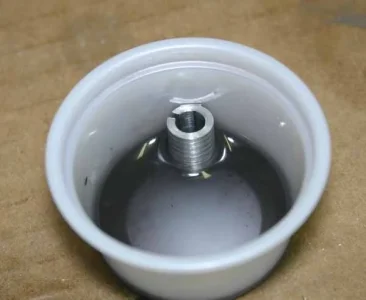
The lap is 6061 aluminum. I don't have copper which is supposedly better. Eventually I'll test against brass & CI but it works. I made simple slits in the lap ID with the scroll saw but forgot to put a fine blade in there so its not the best. I've learned these slots are quite important, it doesn't work as well just counting on the opening slit. The OD looks kind crappy turning but I tried to maintain a rougher finish to help with grip so the lap wouldn't slip, but now I think that's completely unnecessary.
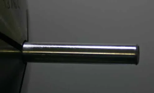
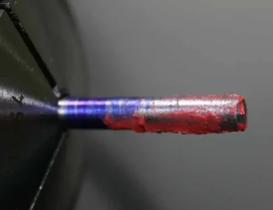
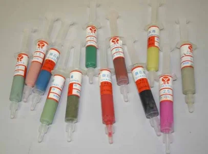
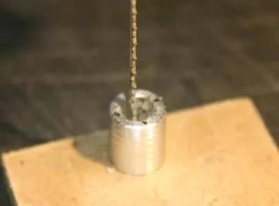
The interesting thing about drill rod (at least the stuff I'm buying), is that it looks shiny & dimension-ally quite accurate, but when you first touch the lap to it with least amount of pressure, you can actually feel some 'oblong-ness'. I pre-blued it with a felt pen to try & take a pic hopefully showing rubbed off shiny hills, but the ink itself washed off. Anyway, after a few strokes which also conditions the lap, it feels quite constant. Just a matter of increasing pressure, stroke some more, clean, check, repeat. I bought a set of Aliexpress diamond lapping paste tubes quite inexpensive & just took a guess at the grit. It is quite creamy but a drop of oil makes it slide a bit better on finishing.
The lap is 6061 aluminum. I don't have copper which is supposedly better. Eventually I'll test against brass & CI but it works. I made simple slits in the lap ID with the scroll saw but forgot to put a fine blade in there so its not the best. I've learned these slots are quite important, it doesn't work as well just counting on the opening slit. The OD looks kind crappy turning but I tried to maintain a rougher finish to help with grip so the lap wouldn't slip, but now I think that's completely unnecessary.
The interesting thing about drill rod (at least the stuff I'm buying), is that it looks shiny & dimension-ally quite accurate, but when you first touch the lap to it with least amount of pressure, you can actually feel some 'oblong-ness'. I pre-blued it with a felt pen to try & take a pic hopefully showing rubbed off shiny hills, but the ink itself washed off. Anyway, after a few strokes which also conditions the lap, it feels quite constant. Just a matter of increasing pressure, stroke some more, clean, check, repeat. I bought a set of Aliexpress diamond lapping paste tubes quite inexpensive & just took a guess at the grit. It is quite creamy but a drop of oil makes it slide a bit better on finishing.
Attachments
-
 IMG_6783_edited-1.webp13.2 KB · Views: 19
 -
 IMG_6788_edited-1.webp8.2 KB · Views: 19
 -
 IMG_6793_edited-1.webp5.2 KB · Views: 19
 -
 IMG_6792_edited-1.webp12.5 KB · Views: 20
 -
 IMG_6790_edited-1.webp9.4 KB · Views: 23
 -
 IMG_6789_edited-1.webp21.9 KB · Views: 21
 -
 IMG_6796_edited-1.webp10.6 KB · Views: 21
 -
 IMG_6797_edited-1.webp20 KB · Views: 20
 -
 IMG_6798_edited-1.webp9.2 KB · Views: 20
 -
 IMG_6784_edited-1.webp9.9 KB · Views: 20
