• Scam Alert. Members are reminded to NOT send money to buy anything. Don't buy things remote and have it shipped - go get it yourself, pay in person, and take your equipment with you. Scammers have burned people on this forum. Urgency, secrecy, excuses, selling for friend, newish members, FUD, are RED FLAGS. A video conference call is not adequate assurance. Face to face interactions are required. Please report suspicions to the forum admins. Stay Safe - anyone can get scammed.

King KC20VS2 spindle rpm readout failure

SSPhoto

Member
Hi everyone,
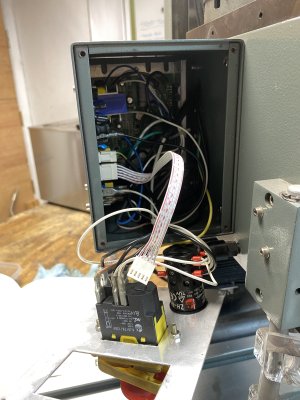
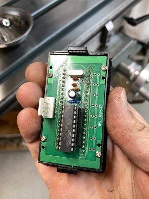
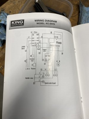
I have a King KC20VS-2 bench top milling machine and the spindle rpm readout stopped working. This happened before when a chip got stuck in the tone ring on the spindle when I forgot to put the cap over the draw bar. I figured it must be the same thing so I took it apart to clean it, but didn't find any chips stuck in there. I still cleaned everything up and re-assembled it, but no luck on getting a reading. My next step is to test all the electronics, but I don't know where to start. The wiring diagram doesn't seem to be much help (see attached photo). Any ideas on where to check power on this to see what my problem is? The mill still runs fine, but it would be nice to know what the rpm is. Thanks!
 

Attachments

  • IMG_3696.JPG
    IMG_3696.JPG
    1.3 MB · Views: 11
  • IMG_3695.JPG
    IMG_3695.JPG
    1.7 MB · Views: 10
  • IMG_3694.JPG
    IMG_3694.JPG
    1.8 MB · Views: 10
I agree the wiring diagram is the pits, it only shows the individual modules.

Look up the chip on the net and locate the power pins. Check that you have power on there. A scope will tell you if the crystal oscillator is running. As far as the chip is concerned its an Amtel version of a PIC chip. It will be pre-programmed so the only way to test it would be to get a replacement chip from the machine manufacturer. Be aware that it is static sensitive !
 
FWIW, inspect (carefully) the pickup and the cable from the pickup to the board it terminates at.

When electronics and mechanics are mixed, > half the problems seem to be mechanical; loose connector, bad contact, bad solder, pinched wire, swarf sitting on pickup, missing magnet, misadjusted sensor, etc.

The tach board might be bad but it wouldn't be my first suspect.

If the pickup and wiring are physically okay. You will need a scope to verify the pulses are arriving at the tach board, and a meter to verify the power supply to the tach board. Be aware in all likelihood that power supply (5-30Vdc?) may have a nasty (as in hazardous) common mode voltage to earth! Some of the cheapy scopes have a signal generator and you might be able to use that to fake the tach signal.

If the display is lit up, just not counting the power supply is probably okay.

There are many variations of those tach boards with different connectors and pinouts. If you search enough you can probably find one that looks like yours and it may show the pinout in the ad.

Here is one variation...
 
Last edited:
FWIW, inspect (carefully) the pickup and the cable from the pickup to the board it terminates at.

When electronics and mechanics are mixed, > half the problems seem to be mechanical; loose connector, bad contact, bad solder, pinched wire, swarf sitting on pickup, missing magnet, misadjusted sensor, etc.

The tach board might be bad but it wouldn't be my first suspect.

If the pickup and wiring are physically okay. You will need a scope to verify the pulses are arriving at the tach board, and a meter to verify the power supply to the tach board. Be aware in all likelihood that power supply (5-30Vdc?) may have a nasty (as in hazardous) common mode voltage to earth! Some of the cheapy scopes have a signal generator and you might be able to use that to fake the tach signal.

If the display is lit up, just not counting the power supply is probably okay.

There are many variations of those tach boards with different connectors and pinouts. If you search enough you can probably find one that looks like yours and it may show the pinout in the ad.

Here is one variation...
Hi Guys,

quote "When electronics and mechanics are mixed, > half the problems seem to be mechanical; loose connector, bad contact, bad solder, pinched wire, swarf sitting on pickup, missing magnet, misadjusted sensor, etc./quote

I agree, but earlier having had a piece of swarf on the board makes me suspicious .
 
Hi Guys,

quote "When electronics and mechanics are mixed, > half the problems seem to be mechanical; loose connector, bad contact, bad solder, pinched wire, swarf sitting on pickup, missing magnet, misadjusted sensor, etc./quote

I agree, but earlier having had a piece of swarf on the board makes me suspicious .
If the power in is okay, and the tach signal @ tach is good, that only leaves the board. I would verify that tach signal before replacing the board.
 
Grizzly lists this as a US$75.90 part plus shipping and GST and likely tariffs. I would be looking at a generic replacement from AliExpress at that price. Even the G0704/G0759 manuals don't show the actual pinouts.
Searching the web for ZD-SX-THL comes up with nothing. (I am interested because mine might go one day)

The bigger problem is that I am confident that the tach pulse is used by the motor controller to maintain constant speed. I notice that when I load up the spindle the speed drops a bit and then recovers. So maintaining the 16 pulse/rev is important IMO
 
Back
Top