• Spring 2024 meetup in Calgary - tentative date Saturday, April 20/2024. Other regions are also discussing meet ups. If you want one in your area get going on organizing it! discussion
  • We are having email/registration problems again. Diagnosis is underway. New users sorry if you are having trouble getting registered. We are exploring different options to get registered. Contact the forum via another member or on facebook if you're stuck. Update -> we think it is fixed. Let us know if not.
  • Spring meet up in Ontario, April 6/2024. NEW LOCATION See Post #31 Discussion NEW LOCATION

Is my Lathe Three Phase?

jmottle

Member
Hi all,

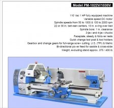
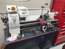
So a few years back I purchased a Chinese lathe from a dealer out in Ontario - a TopTech/Quantum 250 x 500 (equivalent 10 x 22) with an 1100W 120V motor. For the last few years I have been insanely busy running my own business so only just got back to setting up my shop. The lathe works and runs as expected, except for one thing I noticed the other day. When I was in F( forward) the chuck was spinning clockwise. If I put it to R (reverse) it runs counterclockwise, as it should for turning. Thought it was a bit weird, but being a Chinese lathe figured it was a quirk. Tonight while going over the manual I noticed something a bit concerning.

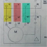
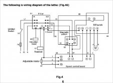
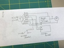
Under the power section it mentions needing three phase power. Had to research what that even was. It specifically notes that if the motor runs backwards, then you're supposed to check the phase connection order. It also says that incorrect connections will result in a hot running motor or will "not run silently and has no power". I ran it with no load at around 1200RPM for 3-4 min and the motor was still cold to touch.

So, I am unclear if the manual is just incorrect, and they shipped the North American bound units with a single phase motor, or if the motor is just not running under ideal conditions. I did notice this motor does hum quite loudly while running, more so at slower RPM. I am not sure if this is normal for this motor type or related to the motor not getting three phase.

This is in a small basement shop on a dedicated 20A circuit, but obviously I can't get three phase power to the house. I read about different converters that can be purchased but at the expense of HP. Really a bit lost here.

Just below the power connection section it also says the following, which I don't understand at all. The shop does not have a GFI breaker, assuming that's what their are talking about.

On lathes of the VARIO type (mine is this type) the frequency converter (driving regulator) might release the FI protected switch of your electrical supply. In order to avoid malfunction, you either need an FI protected switch sensitive for pulse current or AC/DC sensitive. We recommend you use an FI protected switch sensitive to AC/DC. (RCCB, type B are adequate for 1 phase and 3 phase fed frequency converters (driving regulator). An FI protected switch type AC (only for alternating current) is not appropriate for frequency converters. FI protected switches type AC are no longer used.

Help!
 

John Conroy

member
Premium Member
If it is a 120 volt motor it is not 3 phase. The switch at the carriage to select forard or reverse is likely wired with the polarity reversed. The switch does not directly control the motor, it controls a pair of contactors or relays that control the direction of rotation. This allows the use of low voltage DC power (usually 24 volts) at the switch for safety reasons. The switch is likely at the left end of the switch rod mechanism but some pictures will help to sort it out. The switch should have 3 wires on it and 2 of them are reversed. Should be a simple fix.

John
 
Last edited:

jmottle

Member
Thanks! Was coming to this conclusion when I saw 3 phase has a different plug about 2 min before you posted. Pulled an image from the web of my lathe. The emergency stop button has stop and start buttons below the spring loaded door. The three position switch to the left is the direction switch. F/O/R (Forward/Off/Reverse). I can pull the back panel off the to check the wiring, but sounds like it's wired wrong.

maxresdefault-1.jpg
 

jmottle

Member
Just noticed this picture from the web is running in the Reverse position. Seems like this is perhaps by design...
 

PeterT

Ultra Member
Premium Member
Electronics is not my forte, but I wonder if the manual is trying to describe a 3 phase motor, as in a DC commutated, brushless A,B,C type phasing? On my RC brushless motors, I can alter 2 of the 3 wires from the controller to motor & that reverses the direction. I don't want you to fry your electronics, so solicit informed help before doing anything. It might be more complicated in this machine.

Coincidentally I just stumbled on this site & he has a pretty good description of motor types.


John Conroy

member
Premium Member
Sorry, i didnt pick up that the lathe was variable speed. It looks a lot like the 10 X 22 machine that Precision Matthew's sells. They have a very well written owners manual that may help if your manual is the typical chinglish version. On the PM machine the F/R switch is part of a circuit board so changing the direction function by swapping leads at the switch is not be possible. It may be possible to swap the 2 leads right at the motor to change the direction of rotation.

Have a look at page 35 in the manual link at the bottom of this page.

http://www.precisionmatthews.com/shop/pm-1022v-pm-1030v/
 
Last edited:

jmottle

Member
Nice! thanks. Yeah far cry from the poorly photocopied "manual" that came with my lathe. I'd been using the one from the German company Quantum as I think they designed this lathe, but the chinese company TopTech and a few others make it. As you can see from the diagram it's a mix of English and German. I can't tell if it's similar to the PM as my diagram is so poorly described, but I assume it's probably identical to mine in that part of the electronics. It's probably less work to just print my own label for the change-over switch than to mess with the wiring.
 

Attachments

  • IMG_3448.JPG
    IMG_3448.JPG
    80.1 KB · Views: 7

PeterT

Ultra Member
Premium Member
So is there a way to determine if the motor wires extending off of U,V,W go into the corresponding (assume controller block) U,V,W labelled tabs?

Again, don't pull wires unless you are 105% sure. But that might explain it. The problem I've heard, is sometimes the 'correct' wiring doesn't match the manual wiring, which can make for some interesting detective work by qualified electrician types.
 

Attachments

  • 2018-03-18_11-55-35.jpg
    2018-03-18_11-55-35.jpg
    8.2 KB · Views: 2

PeterT

Ultra Member
Premium Member
ok, I'm confused. The PM lathe motor looks to be the same as Busy Bee CX706 because it references the same motor number. It says 'variable speed DC' but (I think) that could still be a brushed motor? PM & BB schematic infers 2 motor wires which would make sense. Vs. 3 wires on 3-phase brushless motor like your manual? That's my whole expertise repertoire - counting wires Haha. .

https://www.busybeetools.com/content/product_manuals/CX706.pdf
 

Attachments

  • SNAG-3-18-2018 0000.jpg
    SNAG-3-18-2018 0000.jpg
    25.3 KB · Views: 4
  • SNAG-3-18-2018 0001.jpg
    SNAG-3-18-2018 0001.jpg
    165.8 KB · Views: 4
  • SNAG-3-18-2018 0002.jpg
    SNAG-3-18-2018 0002.jpg
    41.8 KB · Views: 4
  • SNAG-3-18-2018 0003.jpg
    SNAG-3-18-2018 0003.jpg
    62.9 KB · Views: 3
  • SNAG-3-18-2018 0004.jpg
    SNAG-3-18-2018 0004.jpg
    52.6 KB · Views: 3

John Conroy

member
Premium Member
Nice! thanks. Yeah far cry from the poorly photocopied "manual" that came with my lathe. I'd been using the one from the German company Quantum as I think they designed this lathe, but the chinese company TopTech and a few others make it. As you can see from the diagram it's a mix of English and German. I can't tell if it's similar to the PM as my diagram is so poorly described, but I assume it's probably identical to mine in that part of the electronics. It's probably less work to just print my own label for the change-over switch than to mess with the wiring.


Yeah you're right Peter, I thought it would be like the PM machine but it appears to have a 3 phase motor instead of the DC motor on the PM. If it's like the vfd controlling the 3 phase motor on my mill you should be able to reverse any2 wires to change the direction. But it would sure be alot easier to print a new label for the switch!!
 

jmottle

Member
So without ripping my entire machine apart and tracing circuit paths, I think I'm going go the new label route LOL. Did some wire tracing off the back of the Change over switch and it does not even match my schematics!
 

Attachments

  • IMG_3451.JPG
    IMG_3451.JPG
    118.7 KB · Views: 6
  • IMG_3450.JPG
    IMG_3450.JPG
    79.4 KB · Views: 6
  • IMG_3449.JPG
    IMG_3449.JPG
    77.3 KB · Views: 6

RobinHood

Ultra Member
Premium Member
Do you have a multimeter? If yes, probe the three wires running to the motor. If you get ac voltage, you have a three phase ac motor driven by a built-in vfd. Switch any two of the wires at the motor and you will get the correct rotation.

If this diagram is from your manual for your lathe, then you for sure have a variable speed three phase motor.
https://canadianhobbymetalworkers.com/attachments/img_3448-jpg.2867/
Still confirm with the multimeter. You can’t hurt anything if you switch two wires.
 

jmottle

Member
I only saw two wires (the blue and one of the blacks) that went into the enclosure for the motor. I can't tell if either or both go directly to the motor or if they went to the power line filter.
 

RobinHood

Ultra Member
Premium Member
So the diagram you posted is not necessarily for your lathe.

So it could be a DC motor as has been suggested. A multimeter would confirm that as well. DC motors can have their leads switched to change direction of rotation.

Is there a label on your motor that you could post a picture of?

Maybe printing a new lable is the way to go in this case....
 

jmottle

Member
Took a reading off the back of the direction switch and got 112V AC. I can't get to the motor as it's almost completely encased in the metal shroud and I'd have to move and lift my lathe off the table to do that. I'll need to do that soon enough as as I have to put leveling feet on my stand. Will be building a rolling 4x4 gantry with a chain lift so I can do it then. Need to remove the shroud to install the scales for my DRO. I don't feel that schematic represents my actual lathe from what I saw. Despite this being the manual they provided and hand wrote the factory measured tolerances in.
 
Top