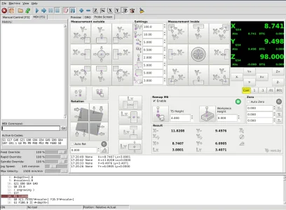
About a year and a half ago my tool setter arrived so I decided to add it along with my touch probe to the PSNG Touch Screen.
Last time I did anything with it was last January. Although I thought I'd done a good enough job documenting things it turns out I didn't. Can't remember how to use it and I'm sure I did have it working correctly.
Anyway. This thread is going to be my rambling on how I got the tool setter and touch probe working the way I want on LinuxCNC.