• Scam Alert. Members are reminded to NOT send money to buy anything. Don't buy things remote and have it shipped - go get it yourself, pay in person, and take your equipment with you. Scammers have burned people on this forum. Urgency, secrecy, excuses, selling for friend, newish members, FUD, are RED FLAGS. A video conference call is not adequate assurance. Face to face interactions are required. Please report suspicions to the forum admins. Stay Safe - anyone can get scammed.
  • Several Regions have held meetups already, but others are being planned or are evaluating the interest. The Ontario GTA West area meetup is planned for Saturday April 26th at Greasemonkeys shop in Aylmer Ontario. If you are interested and haven’t signed up yet, click here! Arbutus has also explored interest in a Fraser Valley meetup but it seems members either missed his thread or had other plans. Let him know if you are interested in a meetup later in the year by posting here! Slowpoke is trying to pull together an Ottawa area meetup later this summer. No date has been selected yet, so let him know if you are interested here! We are not aware of any other meetups being planned this year. If you are interested in doing something in your area, let everyone know and make it happen! Meetups are a great way to make new machining friends and get hands on help in your area. Don’t be shy, sign up and come, or plan your own meetup!

Installing a DRO on my TOS FN20 milling machine

TonyK

Well-Known Member
Premium Member
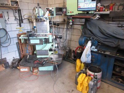
It has been 6 weeks since I had major heart surgery. Over the last 2 weeks I decided to get out into the shop and just do something. Nothing heavy but my mind needed to be worked. My birthday was in February and of course everyone wants to know what I would like for a gift so I said how about paying for a DRO for my milling machine. A few weeks latter it came in from China a Baykuni unit. Cost was about $550 with shipping and taxes. 3 axis slides and readers and display unit. A little background. In 2012 I cleaned up my milling machine and converted it to CNC with DC servo drives and motor shaft mounted Quad Encoders. The software is Mach3 running on Window's XP as it at the time was the most stable for this software. The build also included the ability to run the mill in manual mode. The X screw was worn so I purchased a custom made ball screw to replace the old worn screw on the machine from the UK. The best price was for a metric ball screw but I knew that Mach3 could be programed to get the required counts and convert metric thread to imperial motion on the X axis. At the time there was a board called a Rodgers Board that when installed with another printer port would or I say should allow the encoders to report and display each axis position without the servo's being used. That was a dismal failure and I was left with a problem on the X axis, the scales on the machine and hand wheel were imperial and the screw was metric. So without a lot of messing around the solution was to install a DRO for use in manual mode.

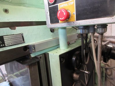
I started on the Y axis as it had a TEE slot for me to mount the scale. The DRO uses magnetic slides of 5um resolution. Installation was a bit trying as the tramming of the slide was to be within .006" before mounting the reader.
IMG_5184.JPG


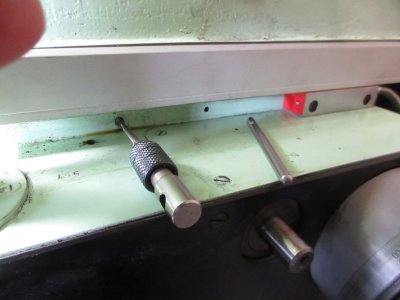
Tapping the mounting holes for the reader became a bit of a challenge, but cast iron is soft so I didn't break a tap.
IMG_5186.JPG

IMG_5187.JPG


The Y axis was the easy axis. But like I said I was in healing mode and my body could only tolerate about 2 hours in the shop each day. In my mind I thought how long can this take, well just like Elon Musk I over state and under deliver. On to the X axis. I contemplated installing this under the table and looked on the internet as some newer TOS machines came with a DRO and the Deckel FP2 & 3 had the X slide under the table, it however presented a few problems.
IMG_5188.JPG


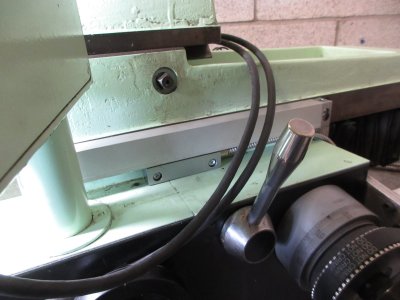
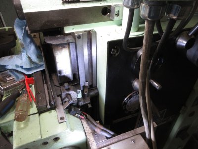
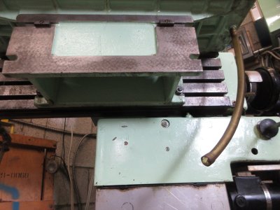
As you can see, the TOS just like the Deckel it is possible to remove the work table. The face now allows larger parts to be mounted and machined and the dividing head to be direct mounted to the T slot face of the machine. Many years ago I would do this by hand, now not a chance. I have a swing davit and a coffin hoist to do the lift, but swinging the dividing head or table into the face and I know that the slide will get hit and damaged. I decided to install the X axis slide where the X axis imperial scale was installed and removed the scale and pointer for the installation. Also the slide would not be mounted to the centre of the axis but to the right side of it. Should work? As long as I now position the reader to the right side as well.

IMG_5189.JPG


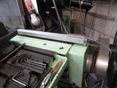
This is the X slide mounted. I had to install spacers so that the reader would clear the machine when the X axis traveled.
IMG_5196.JPG

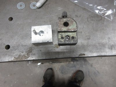
It looks like it will work and it is out of the way. On to mounting the reader. For this I removed the x axis scale pointer and copied it from a block of aluminum.
IMG_5197.JPG


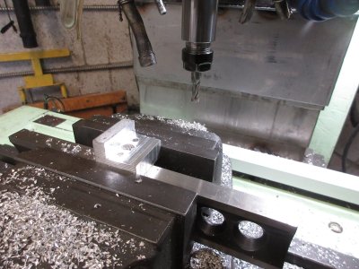
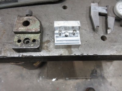
I can tell that this machine was hand assembled as none of the holes lined up nor were equally spaced. To make the part I needed the mill and of course threw chips everywhere I was working.
IMG_5198.JPG
IMG_5199.JPG


This is seat of the pants engineering. Make a little, measure a little then adjust and machine as required. I am moving forward.
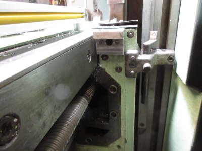
IMG_5200.JPG

The DRO kit came with brackets, that well... just were of little use. However I managed to cut the reader bracket and attach it to my adapter to mount the reader head for the X axis.
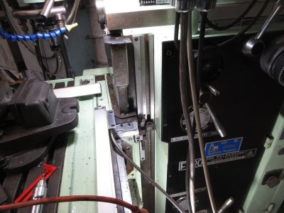
IMG_5205.JPG


So far so good. A week has passed and each afternoon, I have to take a nap, I am gaining. Just to let you know, I don't recommend heart surgery to be on anyone's bucket list. More to come.

TonyK.

Grimsby Ontario Canada
 
Just to let you know, I don't recommend heart surgery to be on anyone's bucket list. More to come.

Nice to see you back posting again!

Your next valve will probably be done by TAVI procedure. You will be up walking around the very next day and hardly know you had a new valve installed! It's amazing. I wish they would do that the first time.
 
Sadly the TAVI procedure will not work for a Mitral valve, open heart is the only option. One valve was in need of repair and once there the other was bad with Barlow disease. TAVI inserts a mechanical valve in series with the defective valve so open heart is not required. Luck of the draw as valves go for me, surgeon say I was born this way. I certainly now have more energy, however the Ablation, kills off part of the heart muscle and now needs to grow back, that process gives endurance, that I am currently working on. Thanks for the comment.

All the best.

TonyK.

Grimsby Ontario Canada.
 
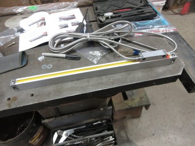
On to the Z axis. As you can see the Z axis is the longest at 13 3/4". Here is a look at the slide on the bench. Although the travel is 13 3/4" the solid sliding way covers that I made reduce that travel by 2" on each side. The machine came with bellows way covers that were in really bad shape so I made up the sliding stainless steel way covers thinking that should the need arise I would remove the cover I needed to do a particular job. It has been 12 years and I have never had to remove the top or bottom way cover to do machine a job.
IMG_5206.JPG


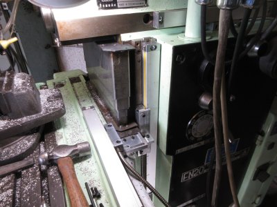
Installation again was similar to the Y axis where I removed the imperial scale and used the Tee slot to fasten the slide. The pointer was removed and adapters were made to attach the Z axis DRO reader.

IMG_5212.JPG
IMG_5213.JPG


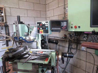
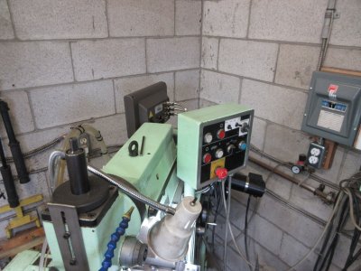
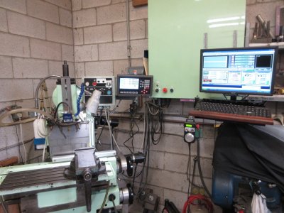
At this point a location for the display has to be considered. Since I have covers for my mill and it is large. I didn't want to upset the size of the cover with the added DRO display, so I attached the bracket and arm to the back of the manual control station and when not in use it can swing back behind the machine so that the cover can be thrown over the machine when not in use.
IMG_5214.JPG
IMG_5216.JPG


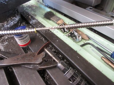
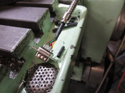
Connecting the slides to the DRO display. As you can see the slides came with a lot of cable. Five conductors plus a shield in an amour jacket that is 9 feet long. Seeing that I am an electrician I could not just coil up the excess and pretend it was not there. So, once each cable was routed the excess needed to be shortened. The jacket is chrome plated steel and a hacksaw will not cut it. The solution was to use a cut off wheel in my Dremel tool. Then cutting the cable and soldering the wires to the slide 9 pin plug.
IMG_5218.JPG
IMG_5219.JPG


This is a shot with the DRO stored and then moved into position.
IMG_5220.JPG
IMG_5221.JPG


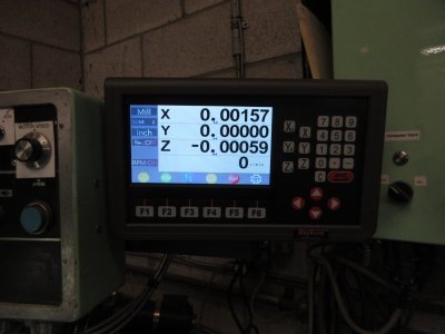
This what the DRO looks like when powered up. The read out is clear and the numbers displayed are BIG for my tired old eyes to read.

IMG_5222.JPG


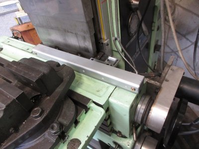
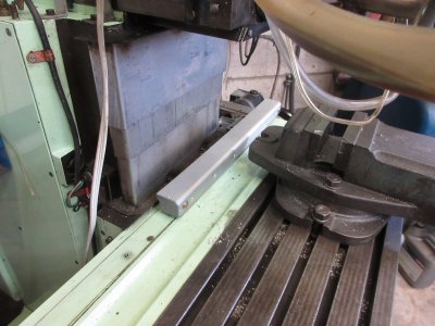
As for exposure to chips and fouling I felt that only the X axis would see this problem presented. The kit does come with covers for each axis, but I only installed on the X axis. Since the way the slide was mounted on spacers I needed to install a silicone wiper on the bottom to prevent the chips from getting under the slide. The big problem is chips falling into the gap between the reader and the slide which has now been addressed.
IMG_5223.JPG
IMG_5224.JPG

These are the original scales and pointers removed for the installation. Now oiled wrapped in wax paper and packed away in a crate with the stock x axis screw.

IMG_5225.JPG


What's left, checking and comparing the Mach 3 encoder position to the DRO and just to make it more impossible comparing to a Starrett 25-441 1" dial indicator. It did not go well.


TonyK.

Grimsby Ontario Canada.
 
Carrying on. When I converted my milling machine to CNC using Mach 3 the problem arises, just how far does an axis really move? Mach3 says it moved an inch, but did it? Mach3 needs to know how many counts from the encoder equals 1". The calculation.

1) Pitch of the lead screw, 2) gearing between the lead screw and motor, 3) how many counts per motor revolution does the encoder transmit.

Since the y and Z lead screw are stock and imperial the numbers are whole.

Y axis to move 1 inch requires 30 revolutions of the motor which presents 256 cycles per revolution and since it is a quadrature encoder that number is multiplied by 4.

Y Axis 30 x 256 x 4 = 30,720 cycles per revolution
Z Axis 60 x 256 x 4 = 61,440 cycles per revolution

Now the kicker the X axis has a metric zero lash ball screw and presents the following numbers.

X Axis 15.228426 x 256 x 4 = 15593.90822

That is the math, but the only way to prove this is with a dial gauge and for this I used a 1" Starrett 25-441 dial indicator. It should be noted that the X axis is zero lash ball screw. The Z axis always has the lead screw loaded and should not present lash. The Y axis being horizontal has about .002" lash and that variance can be programed into Mach3 motor/axis tuning.

IMG_5227.JPG
.
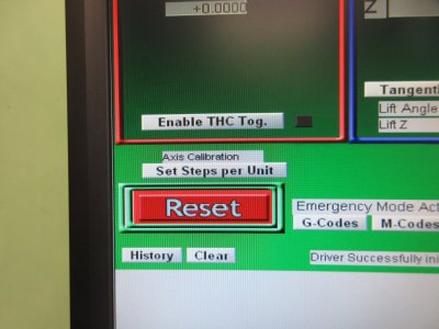
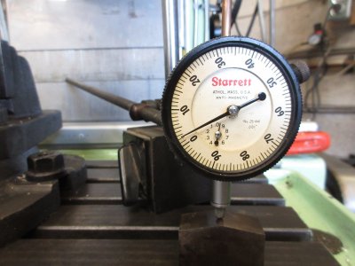
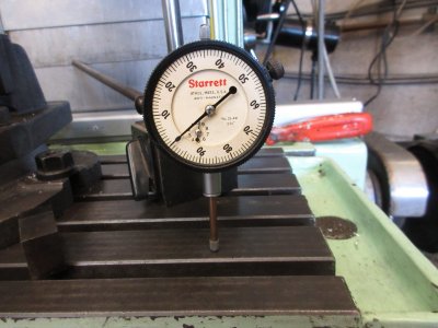
Shown above are 2 Starrett dial indicators that were given to me. The one with the crystal is what I normally use, the other has problems, I do have a new crystal on order for it. Using a magnetic base and the dial gauge I instructed the X axis to travel 1.000" and this is where problems started. Mach3 shows 1.000', the dial gauge shows .998" and the DRO shows .997". Mach3 allows finer axis travel tuning. Axis calibration.
IMG_5244.JPG

A screen opens and you select an axis and just type in the direction and the distance you want the axis to travel. Once the travel has completed, enter the traveled value into the box and Mach3 calculates out the encoder pulses to now equal an inch of travel. This is done several times until the correct value is obtained. I spent a lot of time messing with this only to get no where. So I decided to check my dial indicator with a 1.000" gauge block and found the following.

IMG_5228.JPG
IMG_5229.JPG


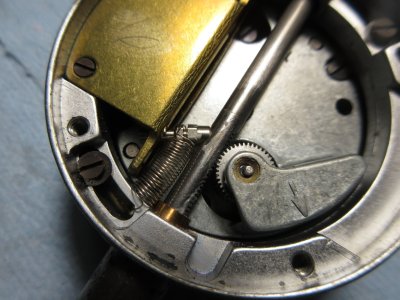
This is the spare that I normally did not use. The dial gauge that I was using was worst, sometimes over and other time under 1.000" So I decided to open the dial gauge by removing the back and found the following.

IMG_5231.JPG

As you can see there is a rack and a pinion gear. The pinion gear bearing is bad. Doing some research there is a jewel in this brass sleeve that is broken. Looking on the internet, I cannot find spare parts but now ask does anyone know if a jeweler can repair this or a shop that I can send it out and have it done? A new Starrett 1" travel dial gauge is pricey, like between $400 to $500. At this point I opened up my other 25-411 to find that the pinion was not engaged with the rack and adjusted it, but testing with the guage block it is still .0005" out and it binds so i have to help it. Relaxing the engagement allows free travel of the plunger, but now the accuracy goes to .002". Thoughts?

At this point I abandoned the 1" dial gauge, I do have others but only .250" and .500" and only use the DRO Between Mach3 encoder axis display and the DRO there is a disparity of .0003". I am going to live with it.

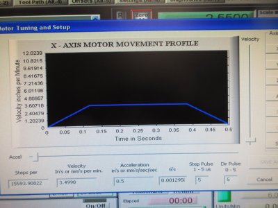
Final X axis counts per 1" travel works out on my machine as 15,604.356644075. Here is a shot of the tuning screen when I was messing with the X axis. Since the machine table is heavy, ( 200LBS )I don't have the travel parameters set very high.
IMG_5241.JPG


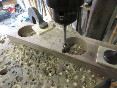
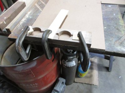
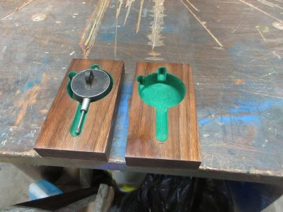
A bit off topic I decided to make holders for the dial gauges rather than let them rattle around in my tool box from black walnut. A little bit about black walnut. Like most hardwood trees the centre or pith of the log is not of much use. Black walnut also has sap wood that is not black but white and can be as much as 3" on the circumference of the log. What I have found is that trees that grow on the Niagara Escarpment ( lime stone) only have about 1/2" of sap wood and thus a higher yield of black wood.
IMG_5236.JPG

Gluing the Masonite back.
IMG_5237.JPG


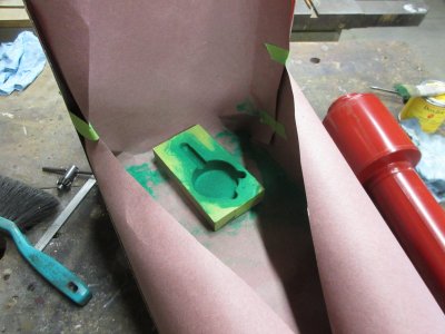
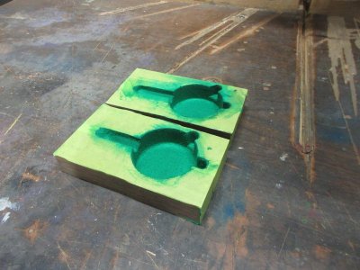
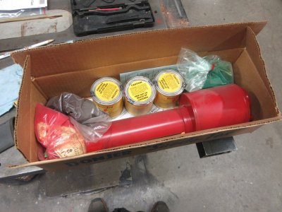
Flocking. The wood blocks are taped to prevent adhesive from touching the face of the holder. Flocking system is from Lee Valley tools. Years ago I made a walnut case for my rifle and used red flocking. It looks very nice. Guys that use 3D printing could really make some nice stuff as well.
IMG_5238.JPG

It takes about a day for all of this to cure. If temped, don't touch it until after 1 day or it will be damaged.
IMG_5240.JPG
IMG_5247.JPG

The walnut was wiped with Linseed Oil.

TonyK.

Grimsby Ontario Canada.
 
Back
Top