• Scam Alert. Members are reminded to NOT send money to buy anything. Don't buy things remote and have it shipped - go get it yourself, pay in person, and take your equipment with you. Scammers have burned people on this forum. Urgency, secrecy, excuses, selling for friend, newish members, FUD, are RED FLAGS. A video conference call is not adequate assurance. Face to face interactions are required. Please report suspicions to the forum admins. Stay Safe - anyone can get scammed.

In Need of: machining small component

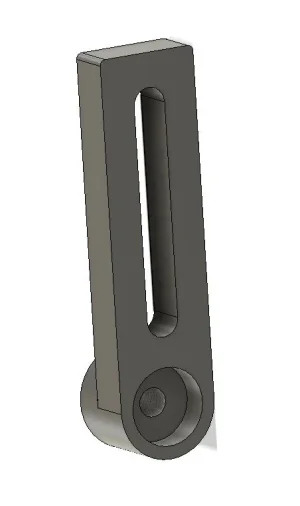
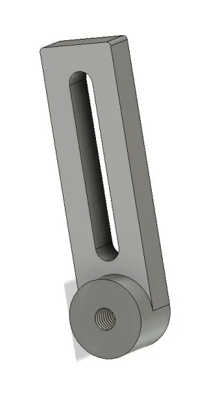
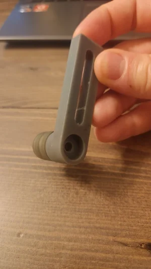
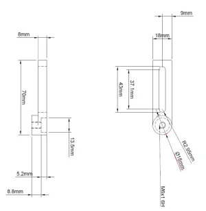
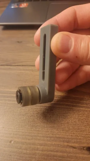
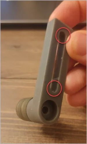
I have drawn up a component and tested it by printing a 3D version. Seems to work for what I need but now need it made from some type of aluminum.

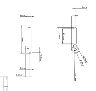
Please see my drawing of the part. I've also linked a 3D images. Remember, this is amateur hour... excuse my drawing/lack of convention. lol

Please advise what this might take.

I'm located in Edmonton.

Thanks!
 

Attachments

  • Tensioner bracket back.webp
    Tensioner bracket back.webp
    10.8 KB · Views: 30
  • Tensioner bracket Drawing.pdf
    Tensioner bracket Drawing.pdf
    111.2 KB · Views: 25
  • Tensioner bracket front.webp
    Tensioner bracket front.webp
    14 KB · Views: 29
Looks pretty straight forward.

The drawing looks like two parts but since I hate welding and especially aluminium, I'd machine that out of one piece of bar - maybe rough cut on a band saw to save a little stock for another job. But I didn't see dimensions so maybe that is just a waste of time.

Seems odd to thread the shaft end. What is the reason for that?
 
Agreed Susquatch! The middle file is a PDF. Shows the length at 70mm so it could be spun on the lathe and trimmed out on the mill in the Rotab! All that said I'm not the guy, have enough on my plate.
 

Attachments

  • Screenshot 2024-08-24 075737.webp
    Screenshot 2024-08-24 075737.webp
    9.6 KB · Views: 17
Agreed Susquatch! The middle file is a PDF. Shows the length at 70mm so it could be spun on the lathe and trimmed out on the mill in the Rotab! All that said I'm not the guy, have enough on my plate.

No way I'd turn that on a lathe unless it is two parts welded together. WAYYYY too much waste that way. I'd do it all on the mill from a piece of solid bar.
 
Nice and easy part, 2 Op CNC mill job. There are a few guys out your way that should be able to tackle that no prob for you. I'd throw my hat in the ring, but shipping from Onterrible would add a substantial percentage to the cost of this part IMO.
 
Nice and easy part, 2 Op CNC mill job. There are a few guys out your way that should be able to tackle that no prob for you. I'd throw my hat in the ring, but shipping from Onterrible would add a substantial percentage to the cost of this part IMO.

Oh. I didn't realize he wanted somebody to make it for him. I thought he was looking for ways to do it and design thoughts. My bad.

It's prolly a few hours work plus materials. Best to find someone in Edmonton to spend a morning or afternoon in the shop and swap lies with.

Easy fun job for someone with a small mill and a rotary table. Prolly a dozen other ways to make it too. Maybe octagon ends without a rotary table.

It's only alumnium. One could even drill the slot ends and the pivot hole and then mount a pivot pin and plate in the vice and rotate the part by hand always using conventional milling. Then mill the slot last. I think that would be simple and fun.
 
Taking a recent Adam the Machinist video to heart, you are buying material and turning it into swarf.
Converting to imperial dimensions (because that is easay stock to find) you are taking .75" and cutting it to .71" wide, ditto with the overall height, .375" stock cut down to .35" (assuming loose tolerances).
Unless that lever really needs to be the sizes drawn you will save machining time and material waste buy using closer to avalaible stock.
 
Nice and easy part, 2 Op CNC mill job. There are a few guys out your way that should be able to tackle that no prob for you. I'd throw my hat in the ring, but shipping from Onterrible would add a substantial percentage to the cost of this part IMO.
A piece that size would be about 3 bucks Canada Post, they can be pretty surprising at times.
 
Taking a recent Adam the Machinist video to heart, you are buying material and turning it into swarf.
Converting to imperial dimensions (because that is easay stock to find) you are taking .75" and cutting it to .71" wide, ditto with the overall height, .375" stock cut down to .35" (assuming loose tolerances).
Unless that lever really needs to be the sizes drawn you will save machining time and material waste buy using closer to avalaible stock.
Tolerances would be the key here. H6 thread and 2 decimal place radius. Possibly not required but.....
 
Same applies to tolerances, tighter tolerances add to time and thus money. Unlikely that tolerance matters here but who knows. H6 for a tap is pretty common so that is a win.
 
Oops , looks like the pdf doesn't show, makes you download. I've screen captured and attached below for dimension reference.
Also took a couple pics of the 3D printed part in hand.

I would think this piece would just need a mill and could be made from 1 piece of stock.
It will be a sliding tensioner with some roller wheels on the end.
It's not going to be a precision component, so tolerances just need to be such that it isn't slack when mounted on a flat plate.
 

Attachments

  • tensioner back photo.webp
    tensioner back photo.webp
    157.4 KB · Views: 21
  • Tensioner bracket drawing.webp
    Tensioner bracket drawing.webp
    16.7 KB · Views: 20
  • tensioner front photo.webp
    tensioner front photo.webp
    154 KB · Views: 20
Just some armchair suggestions
- unless the (presumably) fastener really can position this close to the extremities, you might be able to shorten the slot & leave a bit more meat to the end areas. Not sure what the load or application is but just to the Mark-1 eyeball, it looks kind of close (=weak area)
- why is there a big diameter counterbore on the bar side, when it looks like the bolt comes in from the other side; the round boss side into the threads?
 

Attachments

  • EDT-24-08-2024 10.21.30 AM.webp
    EDT-24-08-2024 10.21.30 AM.webp
    18.3 KB · Views: 5
Just some armchair suggestions
- unless the (presumably) fastener really can position this close to the extremities, you might be able to shorten the slot & leave a bit more meat to the end areas. Not sure what the load or application is but just to the Mark-1 eyeball, it looks kind of close (=weak area)
- why is there a big diameter counterbore on the bar side, when it looks like the bolt comes in from the other side; the round boss side into the threads?
Thanks for the suggestions.
Would the end areas need more thickness than the side areas? I designed it with the thickness being uniform around the fastener.
The reason for the counterbore on the bar side was that to leave me with options to use a lock nut on the back side if threading wasn't an option. I like to leave some room for redundancy so that I can continue to use the component if something stupid happens to the threads....

I think we need to know more about the application.
 
Back
Top