• Scam Alert. Members are reminded to NOT send money to buy anything. Don't buy things remote and have it shipped - go get it yourself, pay in person, and take your equipment with you. Scammers have burned people on this forum. Urgency, secrecy, excuses, selling for friend, newish members, FUD, are RED FLAGS. A video conference call is not adequate assurance. Face to face interactions are required. Please report suspicions to the forum admins. Stay Safe - anyone can get scammed.

Identifying an odd thread.

Susquatch

Ultra Member
Administrator
Moderator
Premium Member
Seems a repeat problem for me is properly identifying an odd thread.

Is it metric or imperial?

Thread gauge can be difficult to use.

Custom threads make everything difficult.

My standard process, is to make an educated guess, then use thread checkers and fastener gauges. But if that doesn't work, I mic the OD or ID, use threading charts to identify possibilities, and test fit if possible.

But quite often it doesn't seem to work very well.

What process do you use?
 
Perhaps an example would help.

I need to make an adapter to fit my mill knee crank. The current thread is buried inside the knee and it's really hard to check it well.

The thread pitch is probably 1.25mm or 20 tpi. Both thread gauges fit well.

The thread OD is
0.787" or 19.75mm

13/16 = 0.812 25/32 = 0.781

Thread wires won't fit in there. Neither will a thread Mic.

Thinking it's a 13/16 - 20. Odd thread, but they do exist.

What to do?
 
If you have room a lot of times I'll hit the tap and die set and see what fits. Other times it's off to the orphan nut and bolt bin to see if anything there fits.
 
Presumably the crank has a dial to confirm physical displacement over N turns assuming its in good shape which should define pitch. Without seeing it up close you are kind of down the path of detective work & educated guessing which might only get you so far. We assume it was made or procured with reasonable accuracy. But is it now worn which lands it somewhere between MET & IMP. Any parts schematics or catalogs of the machine? Logic would apply like probably no metric in an actual Bridgeport & probably no IMP in an offshore. But that can go either way on some metric origin machines Imperialized for the Colonialists & contain IMP parts. And even IMP fasteners which I can only assume they were intending to make the product more service friendly & basically these days have given up which is actually better. And then there is just plain custom for the machine. Take my off-spec PD M30x1 threads on 'new' TCG spindle for example, along with their similarly off-spec nuts. The great thing I don't have to go through the inconvenience of rotating the nuts on the threads, they will just axially jiggle into position :/
 
Your math is a little off, it's 20mm OD.
M20 x 1.25 taps and dies are readily available.

I already ordered a 20mm - 1.25 tap and die too.

The purpose of this thread is methodology. How do YOU identify a thread?

Presumably the crank has a dial to confirm physical displacement over N turns assuming its in good shape which should define pitch. Without seeing it up close you are kind of down the path of detective work & educated guessing which might only get you so far.

What a great idea. But sadly, it won't help. Can't crank the knee up or down when that thread is visible.

We assume it was made or procured with reasonable accuracy. But is it now worn which lands it somewhere between MET & IMP.

I doubt that part wears.

Any parts schematics or catalogs of the machine? Logic would apply like probably no metric in an actual Bridgeport & probably no IMP in an offshore.

Ya, it's a Hartford Bridgeport Clone made in Taiwan. It's full of both metric and Imperial parts some copied from BP, some just what they used. No parts catalog that identifies that thread.
 
So, is this an example or kinda real? As @MrWhoopee just posted while I am single finger typing, likely 20mm, which is about half a thou. bigger. 13/16 is .812, this is .025 +/- bigger then the measurement. A lot of wear. A 1.25 pitch is a metric pitch, in hand with a 1.0 and 1.5 etc. If this measurement is taken at the end of a shaft thread not subject to wear, would seem to go back to 20mm. And as @PeterT also posted where was machine made and maybe when, and is it/could it be a replacement part, shop made to replace worn out part, made “up” specs. Is this thread used elsewhere on the machine? This seems to lead to having to make a test piece, threaded, if it will thread together 2 full turns, likely good, if 3 turns, probably are good.
Yes, not being able to get good access and poor room for test tools is a bear that requires extra time, work and sometimes troubles. What it should be is not always what it is, applies to lots of things.
International equipment would sometimes times have a thread that would be 1 more per inch then “normal” on a piece, just to keep things interesting and keep sales.
And another post.
 
Wait until you run into British Wittworth, 1/2"-12, I don't even have a 12 tooth on my thread gauge.
Could figure it out what it was, manage to sort it out.
All I wanted to do was chase some badly mangled threads, you have the choice of an expensive tap that will last 2 life times even though I'll never use it again, or a $20 tap that you know is going to break off in the hole.

I just use these 3 tools.
 

Attachments

  • IMG_1531.JPG
    IMG_1531.JPG
    955.2 KB · Views: 3
So, is this an example or kinda real?

It's real and an example too. It's just the latest one I hit. I've ordered taps and dies to help nail it down.

But the real reason for posting this thread is to see what process others use. I seem to have this problem fairly often. So it struck me that I'm not the only one who must encounter the problem and there might be guys who do it often enough to have developed a process they would like to share.

As @MrWhoopee just posted while I am single finger typing, likely 20mm, which is about half a thou. bigger. 13/16 is .812, this is .025 +/- bigger then the measurement. A lot of wear. A 1.25 pitch is a metric pitch, in hand with a 1.0 and 1.5 etc. If this measurement is taken at the end of a shaft thread not subject to wear, would seem to go back to 20mm.

It's an old machine but it's not likely that this thread has seen a lot of wear. It simply isn't regularly used. It's just tightened and forgotten. I need to make an extension for it so I need to know what the thread is.

And as @PeterT also posted where was machine made and maybe when, and is it/could it be a replacement part, shop made to replace worn out part, made “up” specs. Is this thread used elsewhere on the machine?

Could be, but I doubt it. It's also a factory part so it's not likely a made to fit thread.

This seems to lead to having to make a test piece, threaded, if it will thread together 2 full turns, likely good, if 3 turns, probably are good.

Yup, that's where I am at now.

International equipment would sometimes times have a thread that would be 1 more per inch then “normal” on a piece, just to keep things interesting and keep sales.
And another post.

Let's hope that isn't the case!
 
For the really tough to identify, I will get my magnifier out and some good lighting. I measure the O.D = metric or imperial or ?
I will measure over the length 1" or more and count how many threads there is and average it to a single pitch. Then figure out if it is metric or imperial or ???
If the threads are large and deep enough I will try figure out which of the 60 or 55 threading tool fits best. That is not easy to do with fine threads.
For internal thread I usually turn a wooden plug just a hair larger than the i.d. thread it in to get a impression of the thread and again measure a long section and average to 1 pitch. metric or imperial or ?? then look up the machinist hand book and see what are some of the possibilities. Turn and thread a sample screw on the lathe to the machinist handbook specification using the over the wire method and test for fitment.
 
For internal thread I usually turn a wooden plug just a hair larger than the i.d. thread it in to get a impression of the thread and again measure a long section and average to 1 pitch. metric or imperial or ?? then look up the machinist hand book

What a fantastic idea! I'll be using that method someday soon!

The rest of your method is similar to mine except I like to buy a sample thread or a tap & die to test fit with.

A magnifying glass is imperative as my one remaining good eye is nowhere near what it used to be!

Great post! Thank You!
 
After buying the BA set, I realized I didn't have a BA thread gage, so that's on it way from somewhere via Amazon; also got a BSW gage and already had Acme so should be good with regard to thread pitch and profile.

My process is pretty much like yours, Sus, but I try the various "Thread Checker" sets I have before delving into MH. When I still can't figure it out, I'll try reaching out to the manufacturer (like I did for that Starrett No.196 post) or search the web for the part. If I'm still flummoxed, I'll stoop to asking here, HMEM, H-M & HSM. By the time I get an answer it will probably be A) I made a mistake in my measurements or B) I will have forgot why I searched/asked :rolleyes:
 
My process is pretty much like yours, Sus, but I try the various "Thread Checker" sets I have before delving into MH.

Actually, I do that too. I have a few different thread checkers I like. The top four are my working set, but I have some nice ones in the house too.

20250210_161857.jpg

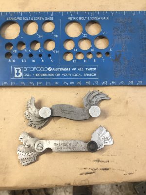
I also love the metric and imperial screw checkers below. But they only work for small screws. I recently got a necklace from Ali and I like it too for bigger fasteners. It's sort of like the ones at the fastner stores but easier to store in a home shop. Mine just hangs on a nail.

20250210_162101.jpg

I don't really have a problem with the really big stuff. They are almost always sorta obvious.

You remind me that I asked for a process but didn't volunteer my own for criticism. Given the regular problems I have, maybe that's how I should have started this thread.

1. Attempt to identify the pitch with thread gauges, counting teeth under a magnifying glass, or sometimes like my caliper repair, under a microscope. Sometimes hold the thread up to a tap if you have one with the right pitch. Write down the possibilities as it's not always obvious and if I don't write it down I'll forget and have to start over.

2. Measure the OD or ID and subtract a wee bit for thread crest and valley based on the pitch size - more for big threads. Compare to the obvious threads on the wall chart, in threading tables, and as a last resort in MH.

Use thread wires or a thread Mic on external threads along the lines of what @PeterT suggested above. Curse at internal ones. Here is where @fixerup's wooden dowel will keep the air from turning black and blue in my neck of the woods. (Ya, I love that idea!) Thinking it might work on hard to reach external threads too by screwing a wooden tube on and off, and then sectioning it.....

If the thread is not common or obvious, I make a sample gauge screw or gauge hole to test fit. Often, that means buying a tap and die (like this time).

On very rare occasions, I have calculated how many threads it takes to be out one complete thread and then measured over that length. This z-axis thread might be one of those times.

I've not had good success watching YouTube or searching the internet. Generally, I find that those kind of threads are easy peasy anyway. It's the rare, unusual, and custom threads that drive me crazy. I encountered a custom thread on a BXA tool holder of all places a year ago or so. Drove me bonkers! I made a copy by single point threading, and it worked, but why the hell would they do that to us! That must have cost them money to do!
 
So has anyone ever tried putting it in the lathe with an indicator on the threads to try matching different threading feeds?
( Had to ask I’m outside the box again )
IMG_0485.gif
 
I thought you pew-pew aficionados all knew about Cerrosafe. Female thread? Fill with molten Cerrosafe, unthread, wait a bit for it to return to full size. Measure thread pitch.

I’ve done this with pewter, but it makes a mess and you need to be finicky about cleaning the existing threaded item so the pewter doesn’t stick or ignite any oil or flammable contaminants.
 
So has anyone ever tried putting it in the lathe with an indicator on the threads to try matching different threading feeds?
( Had to ask I’m outside the box again )
View attachment 59607

Never. The other way around yes. Your way, never. The thought of using my lathe threading chart as the litmus test gives me diarrea. LOL!
 
I thought you pew-pew aficionados all knew about Cerrosafe. Female thread? Fill with molten Cerrosafe, unthread, wait a bit for it to return to full size. Measure thread pitch.

Not really. It's a good idea though. I have several pounds of cerrosafe. I'd just be too concerned about a thread defect or a very minor negative taper jamming it up. The stuff doesn't relax in tenths of an inch. More like just a few thou.

I’ve done this with pewter, but it makes a mess and you need to be finicky about cleaning the existing threaded item so the pewter doesn’t stick or ignite any oil or flammable contaminants.

I'm thinking you are liking the wooden dowel or pipe as much as I am......
 
Silly thought, assuming you have a DRO on the lathe.

Do the dowel or cerrosafe routine, or moldable wax. Could even use spray foam and plastic cling wrap.

Put a threading bit in the tool post. With the lead screw disconnected, move the carriage and bit to a nice snug fit into the molded thread. Zero the DRO. Move to the next thread, write down the DRO reading. Repeat until you gave ten readings. Average the readings, you now have the thread pitch.
 
Back
Top