• Scam Alert. Members are reminded to NOT send money to buy anything. Don't buy things remote and have it shipped - go get it yourself, pay in person, and take your equipment with you. Scammers have burned people on this forum. Urgency, secrecy, excuses, selling for friend, newish members, FUD, are RED FLAGS. A video conference call is not adequate assurance. Face to face interactions are required. Please report suspicions to the forum admins. Stay Safe - anyone can get scammed.

How would you repair this gear?

mikoyan31

Stewie
Now that I have the concrete slab poured and the lathe bed pretty well positioned where I want it, I'm in the process of reassembly. In doing this I'm disassembling and cleaning a century worth of oil, grease, crud and paint from the sub assemblies. Oy the paint! I've counted so far at least three different colours, all slapped on with a brush including over things it shouldn't have been, like the lead screw and apron controls. The good thing is nothing was properly prepped so it basically flakes off with a scraper quite easily. But I digress.

The machine is a Fay and Scott 14x40 (give or take) metal lathe from, and I am guessing, the end of the 19th century.

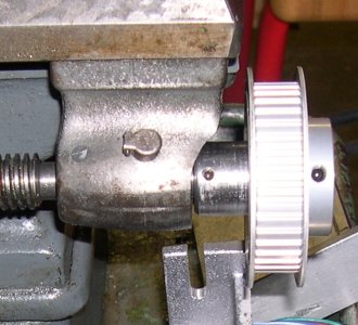
Disassembled the apron and realized the bevel gear for the clutch drive (key drive?) didn't look right. Copious de-greasing later and this is what I have.

PXL_20221024_131737207.MP-X4.jpg
PXL_20221024_131747111.MP-X4.jpg


Well I found some of those teeth, in the sliding drive gears.

PXL_20221024_131802606-X4.jpg


PXL_20221024_131810622.MP-X4.jpg


PXL_20221024_131818284.MP-X4.jpg


As crazy as this may sound, this is the first actual damage and wear that I have found. Plenty of neglect but that has cleaned up quite well.

I've watched YouTube videos of the folks like Keith Rucker and David Richards repairing cast gears by brazing the broken areas and machinating the teeth back in. Those are spur gears though and usually larger. Also I don't have the tooling or know how at this point to actually do that. I'm thinking my options are:

- Braze it up like I see in the videos (it is a cast iron piece I believe) and then go at it with a a triangular file/needle files and rebuild the teeth that way
- Take it/send it to a machinist somewhere and have them re-machine it
- Troll EBay or other sites to see if I can find these pieces or a whole apron (HAHAHAHAHAHAHA! Right!)
- Bite the bullet and have a whole new set made up from scratch

I'm open to suggestions.

As an aside, trying to put this old lathe back in some semblance of working order has quite frankly nearly had me in tears more than once. Not the actual work, but the fact that this is very obviously a well made piece of machinery that was built and put together by people who also obviously took pride in their work. Then it was used, abused and neglected for years by people who didn't seem to give a shit. Makes me wonder what kind of work they turned out using it, and probably blamed the tool when it was crap.
 
Well.... you have a couple of options which depending on your budget or patience or skill us going to be your driving factor.

New gears made, great but $$$$$$

Now if you or friend can weld, build up the broken areas with welding (I would likely recommend TIG and using SS filler as its cast, look it up on why). Use the exist good portion of the teeth as a guide and go at it with a file. This is good option but will try your patience and skill. Best case you learn (master) TIG and learn how to file, worst case a gear goes through a wall.
 

terry_g

Ultra Member
If your not confident with your TIG welding skills I would go with building them up with brazing rod.
Build a jig to hold the gear securely in the vice for brazing and filing. I would use a large wide course
half round file that would fit between the gear teeth. Welding or clamping a handle on the opposite
end of the file so you can get good pressure and control of the file would speed the process.
Might be an idea to grind the sides of the file so you don't cut into the root of the gear teeth.
 
Last edited:

Mcgyver

Ultra Member
Ouch that is nasty. imo its beyond a braze then machine repair.

Making bevel gears is quite different than spur gears. They are generated on a special machine (even hobbing doesn't work). For this reason, the odds of walking into a machine shop and having someone know how to approximate a bevel gear I'd guess are slim. However they can be approximated, the techniques are covered in Ivan Law's Gear book (modellers and such can tolerate dodges). With a slow speed application like this, it might be fine.

Just those two mate? if so, that is good news as you might be able to use any pair about the right size.

- Like Darren suggested, getting a stock two about the right size is a good option. That would be quickest and easiest if the price isn't stratospheric

- Get a price from these guys.....being offshore maybe they are low cost.
https://www.bevelgeartw.com/?gclid=EAIaIQobChMI3pHD2p_5-gIVdf3jBx1WpwT1EAAYASAAEgLdK_D_BwE4

- Use the money to get a dividing head and figure out making the approximated verion of a bevelgear....even the most complex thing is just a series of little steps.
 

WilliamR

Active Member
Might be able to buy stock gears from Boston gear or similar and make your own assemblys easier than repairing them.
@Darren What a resource.

@mikoyan31 If Boston gear didn't work out for you or it starts turning into bigger project than you thought, this guy on local facebook marketplace might be an option. Maybe get a quote?

"Precision 2D cnc cutting by wire EDM any metal better than water cut or laser and up to 24 inch profile thickness with no heat affected zone, hard to machine types of shapes . prototype parts, replacement ,repair parts."
271880080_5287791797916551_7885721891567455913_n.jpg

271904820_5138989249446874_3326007610440068704_n.jpg
 

YotaBota

Mike
Premium Member
The spur gear appears to be pressed and pinned into the bevel gear, am I seeing it correctly?
 
Last edited:

mikoyan31

Stewie
There are in fact three gears, the large and two identical of the smaller. The smaller gears actually engage with shift forks for forward and reverse feed. I'm starting to lean towards the Boston Gear adapt-it-to-make-it-work idea. I ran into another problem with the clutch that made me put everything down and just walk away for a while.

I am considering putting the apron back together without these gears and the clutch. I still have the 1/2 nuts, I know not best practice, and I can still manually feed without the power feed. Frankly I'm a bit discouraged and need to take a break from the project for a bit.
 

SomeGuy

Hobbyist
Crazy idea...

Make them in CAD, 3D print them, create molds from the 3d prints, re-cast new gears?

Heck...you might be able to send it out for metal 3d printing relatively cheap?
 

YYCHM

(Craig)
Premium Member


jcdammeyer

John
Premium Member
Or alternatively, change the lead screw over to a ball screw and add an ELS. I took the half nut off my Gingery years ago and turned a custom ACME 10TPI screw and nut. Added my ELS. Haven't looked back.

Same with the South Bend. Added ELS for just the Z axis. Haven't engaged any gears for 8 years or so. So much quieter to operate too. And I can turn metric or imperial right up to the chuck jaws without touching them. Hard to do sitting on the half nut lever.
 

jcdammeyer

John
Premium Member
To be fair the South Bend was modified to add the motor at the end of the stock lead screw. I must admit I do sometimes disengage the half nut and use the hand wheel to move the carriage faster than the 2:1 stepper motor drive. I bought a surplus lead screw hanger and milled some of it away so I could attach an adapter.

The fundamental issue is that the half nut and lead screw weren't meant for high RPMs to be able to move the carriage at the speed the handle with rack and pinion does.

Were I to switch to a ball screw I'd go 5 TPI and an AC servo so I could move the carriage faster than the hand wheel but still have the resolution with the encoder on the back of the AC servo.

As yet I haven't needed Electronic Gear Screw (which is what the Arduino systems are) and can get away with a single pulse per rev on the spindle. At least for the quality threads my 1942 SB will create.

But in either case, unless your lathe is a collector item and you _must_ have it stock, a CNC like solution is usually better.
 

Attachments

  • ModifiedLeadScrewSupport.jpg
    ModifiedLeadScrewSupport.jpg
    310.4 KB · Views: 1

Dabbler

ersatz engineer
Braze it up like I see in the videos (it is a cast iron piece I believe) and then go at it with a a triangular file/needle files and rebuild the teeth that way
you can do it that way. it will take time - a fair bit of it. But if you really like hand work (I do) then I say - go for it!
 

mikoyan31

Stewie
So, I've been doing a little reading. Looks like an ELS might be a good idea. In a way I kind of like the idea of marrying 21st century DIY to a 19th century machine. I just suck with electronics though. I picked up one of those Arduino kits (make EVERYTHING) and beyond the basics promptly screwed it up. Odd considering I work with servers and networking day in and day out. Perhaps too close to my actual job.
 

jcdammeyer

John
Premium Member
So, I've been doing a little reading. Looks like an ELS might be a good idea. In a way I kind of like the idea of marrying 21st century DIY to a 19th century machine. I just suck with electronics though. I picked up one of those Arduino kits (make EVERYTHING) and beyond the basics promptly screwed it up. Odd considering I work with servers and networking day in and day out. Perhaps too close to my actual job.
Although the Arduino and bits and pieces including really cheap encoders all come from China there's a lot of work required to put it all together and package it. A certain amount of software intervention for programming etc.

Mine wasn't made in China so is more expensive and only uses 1 PPR encoder pulses. That means you cannot turn the spindle and have the carriage track the way gears do. ie. Not electronic gearing. But encoder with two timing belt pulleys, timing belt, mounts etc. are way more work than a simple magnet +sensor or slotted disk + sensor. And mine can run a lathe faster than about 1800 RPM although yours, like my South Bend probably can't go that fast anyway (or shouldn't).

One of the E-Leadscrew group members created a 3D printed box for mine.

I used to supply the carriage axis stepper driver as part of the kit but the two drivers now cost more than a complete micro-stepper driver from China so that's no longer an option.

This is not an advertisement. I've never earned any money from these. They've always been sold at my cost of parts and if assembled and tested I paid my son $25/hr for the 3 hours it takes and passed on the $75 cost. Now since the boards are older and harder to solder it's easier for me to solder them up with water based flux and test them first. Then sell them for the original $150 price w/o the assembly charge since I'm just trying to get rid of inventory rather than have it go to recycling.

I did start on an electronically controlled back fence for my 3:1 sheet metal tool but that project (#42) isn't done yet. I was going to use the ELS with the built in stepper driver for the fence motion and even be able to enter the K factor of the sheet metal and the direction of the metal grain so it could compensate. Maybe next year...
 
Look brazing or welding the gears as mentioned earlier is still not a bad idea. The reason you have parts of the gears left to act as a cutting guide. Even the dreaded bevel.

Don't over think it. Just use a straight edge and keep things in line. The speed at which you run and the fit is a loose running fit and the tolerance or accuracy is based in the direction of turning and feed.

Again you are not working to modern ultra high precision tolerances but older worn machine tolerances.

Now if you want CNC thats a different story.
 

mikoyan31

Stewie
Morning all.

So for kicks and giggles I popped by the local machine shop yesterday. When I told him what the gears were, he winced. Yeah, that was some serious crashing. Anyway, I expected either "Nah we don't want to do that" to "Sure it will be $$$$$$$ to do that." What I got was "I know a guy who knows a guy who has all sorts of old gears like that, I think we could probably get something that could be modified to work." So I left everything with him for a few days. In the interim, since I have it all apart, I'll see about stripping the six coats of brushed on horrible paint off the parts. You can even see the drips where the paint ran.
 

trlvn

Ultra Member
Are you sure those gears are cast iron? From the pictures, they look more like Zamak, to me. If so, there is absolutely no way to braze or weld them for repair. Zamak melts at a very low temperature, something like 700 F depending on the exact alloy. Whatever the number is, it is way less than the heats needed for welding or brazing.

If the gears are Zamak and you replace them with something tougher, you may need to think about failure modes. The Zamak gears may have intentionally been designed as the weak link that would fail 'gracefully'. As opposed to a gear box splitting in half or something equally catastrophic! If you go with, say, cast iron gears, you might want to use a shear pin in the setup.

Craig
 

mikoyan31

Stewie
Well, I *believe* and I am more than willing to be proven wrong, that the lathe predates the use of Zamak. Also they're magnetic and obviously the blank was cast as it still has the pattern or part number H97 in the back. That's what makes me think they are iron.

There are absolutely no other safety features on this lathe, either to protect the operator of the machine itself. The lack of a sacrificial weak point isn't surprising. Or, as you say, maybe this gear WAS the sacrificial part. Considering how much I had to tear apart to get at it though, I would doubt it. My experience with old machinery, especially old industrial machinery is that, if asked to, it will happily kill you and thoroughly wreck itself, perhaps both at the same time. Safety and well being of operator and machine resides solely between the operator's ears.
 
Top