Hi All,
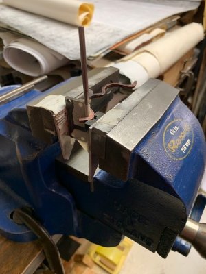
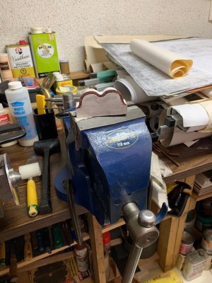
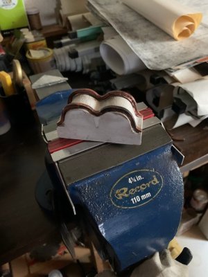
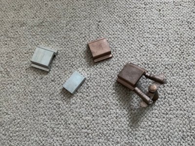
More creative bending to finish fit the front rib. The very tight end bends were the worst. One more to go.
One thing I didn't mention was, when bending the straight blank piece, I started the forming in the centre and slowly worked out to each end. And sometimes I had to bend the copper into a shape I didn't want just to be able to get access to bend anything at all.
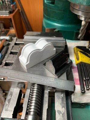
When finished, I will glue the end ribs onto the wood body.
More creative bending to finish fit the front rib. The very tight end bends were the worst. One more to go.
One thing I didn't mention was, when bending the straight blank piece, I started the forming in the centre and slowly worked out to each end. And sometimes I had to bend the copper into a shape I didn't want just to be able to get access to bend anything at all.
When finished, I will glue the end ribs onto the wood body.