• Spring 2024 meetup in Calgary - tentative date Saturday, April 20/2024. Other regions are also discussing meet ups. If you want one in your area get going on organizing it! discussion
  • We are having email/registration problems again. Diagnosis is underway. New users sorry if you are having trouble getting registered. We are exploring different options to get registered. Contact the forum via another member or on facebook if you're stuck. Update -> we think it is fixed. Let us know if not.
  • Spring meet up in Ontario, April 6/2024. NEW LOCATION See Post #31 Discussion NEW LOCATION

Harmonic Drives

jcdammeyer

John
Premium Member
Perfect fit. Turns smoothly.
Slight ticking sound. Here's why:
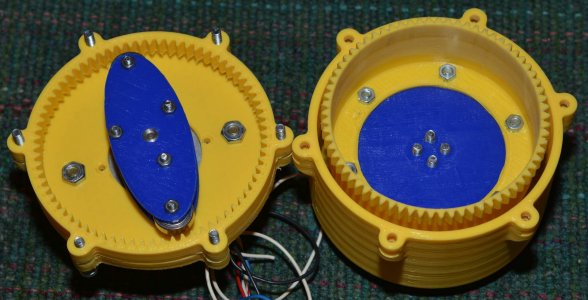
This is the bottom of the cup.
CupBottom-1.jpg

And here's a close-up:
CupBottom-2.jpg

It's clear that the bonding between filaments is pretty crappy. I don't know how much of that is my printer. How much is the parameters for slicing into G-Code. Anyway the ticking I get here is the crack opening/closing between a couple of the strands where there is a crack. This is supposed to be 1mm thick. Any more and it's really stiff.

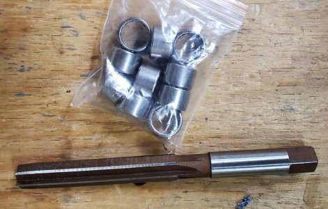
Better to use PETG or perhaps Nylon but at the moment I can't actually print those. In the long run I want to make the cup from steel with my M0.5 gear cutters. Special tool to spin the cutter inside the cup will be required.

So many projects...
 
Last edited:

jcdammeyer

John
Premium Member
A friend of mine is going to try printing it on his CR-10S. See if he can slice and dice it into a nicer cup. Meanwhile the 5min epoxy has been hardening (as much as 5min will -- which is a good thing here) and I'll take another look at it in a few hours.

Meanwhile my supervisor (the one with the tail) wants to go walkies. Actually we don't go for doggy walks; more like doggy ambles. She's 11 and a half years old, missing a spleen and almost 4 years past her "she has between 1 to 3 months" point.
 

jcdammeyer

John
Premium Member
The 5 minute epoxy has had 8 hours to set. I can still dent a bump with my fingernail so it's not too hard (ie. a bit flexible). No more ticking sounds as it turns. And it turns so smoothly.

With cleanly formed gear teeth this time it seems to have a nice engagement. Of course the teeth are also tapered by 2.5 degrees but over 13mm that's not that much.

The key to this project will be the cup gear. The second major issue will be balancing the wave generator holding the bearings.

The hub with the tapered roller bearings can be a cast iron trailer hub where the 4 bolts that hold the wheel serve as the drive mounting bolts. It's the shaft that does the turning while the hub is held fixed. Next time they go on sale at Princess Auto I'll look into getting one. I just missed the 50% off sale on replacement bearing sets. (1" shaft) and they are now back up to about $40.
 

jcdammeyer

John
Premium Member
Ever had that "Oh Crap! Now what?" moment?
Every time I take the drive apart and remove the shaft and cup assembly the top tapered inner bearing falls out. I'd always planned on putting a cover or an oil/grease seal in place but haven't gotten to that yet. However as it turns out flathead 5mm screws have heads that are way too large and would interfere with the drive hub. What to do?

So I printed a shallow cover with counter sink holes for 3mm flat head. Trouble is the holes are ready for tapping 5mm. Oh wait... I have a lathe... and 3mm taps and a 2.5mm drill.

All that's left to do is epoxy the inserts in place.


Inserts-3mm.jpg
 

jcdammeyer

John
Premium Member
While I was making the inserts the 3D printer was busy making a tool for me.
Here are the parts that make up the drive section of the EWG Harmonic Drive. The red hub is threaded onto the shaft and locked with a lock nut. All 3D printed. The shaft now has an aluminum insert to deal with over torquing this nut with the needle nose pliers. As it is it's hard to decide just how tight to torque this but that's a different story.
DriveHubParts.jpg

I'd thread on the hub, thread on the nut as far into the hole as I could and then use pliers to tighten. Another mistake that will be easy to correct is the yellow shaft is just a tad long. Don't want it protruding outside the hub. Anyway, a real pain tightening this.
DriveHubNutInPlace.jpg

So instead I 3D printed a tool.
DriveHubNutSocket.jpg

Beats buying one.
 

jcdammeyer

John
Premium Member
I've ordered some pilot bearings to be installed in a similar way that a manual transmission input shaft is aligned into the crankshaft dealing with the two shafts sometimes turning different speeds.

Here's a drawing of how the stepper motor driven shaft that turns the wave generator lines up with the output shaft that is turned at a 36:1 ratio. The External Wave Generator cup is pretty large with the 6 ball bearings and can turn up to 1000 RPM so balancing of that part may also be a requirement.

Questions are welcome.
PilotOutputShaft.jpg
 
Last edited:

jcdammeyer

John
Premium Member
Gosh, two months have gone by. Waiting for the needle pilot bearings and the reamer. The shutdowns in China slowed delivery. Now I have both with one teensy weensy problem. The 12mm reamer I ordered fits the ID of the needle bearings; not the OD. So I can't start on the next stage until the 16mm reamer arrives. I had ordered a set that included the 16mm but it was cancelled by the supplier after they were part of the shutdown. After that the 'store' was always on vacation. So instead of ordering a set I ordered 12mm instead of 16mm.

Anyway, until the reamer arrives I can't really work on this project and at the moment the bench (table saw surface) is covered in the S100 computer rabbit hole.
 

Attachments

  • NeedleReamer.jpg
    NeedleReamer.jpg
    180.7 KB · Views: 2

jcdammeyer

John
Premium Member
I've ordered some pilot bearings to be installed in a similar way that a manual transmission input shaft is aligned into the crankshaft dealing with the two shafts sometimes turning different speeds.

Here's a drawing of how the stepper motor driven shaft that turns the wave generator lines up with the output shaft that is turned at a 36:1 ratio. The External Wave Generator cup is pretty large with the 6 ball bearings and can turn up to 1000 RPM so balancing of that part may also be a requirement.

Questions are welcome.
View attachment 22397
A while has gone by since I even looked at this project. Easily be another month or two before I can restart it but I have question.

I've attached a 3D PDF of the output coupler and I have the 12 mounting holes set up as 4.2mm clearance for 4mm screw (and tap) from the bottom and the rest is drilled for 4.0mm x 0.7mm tapping. The thickness of the entire disk is 15mm and it really doesn't need to be tapped for the entire 15mm; I think 5mm is enough.

Tapped from the bottom the question is what is the best way to do this? It's too large fit through my rotary table. I'd likely have to mount it in such a way so it extends outboard of the mill table. Then just use XY positioning for the holes.

Any other suggestions?
 

Attachments

  • OutputCoupler-6003.pdf
    788.1 KB · Views: 3

Susquatch

Ultra Member
Administrator
Moderator
Premium Member
Tapped from the bottom the question is what is the best way to do this? It's too large fit through my rotary table. I'd likely have to mount it in such a way so it extends outboard of the mill table. Then just use XY positioning for the holes.

Any other suggestions?

If this were mine, I'd make a cheap fixture to mount it flange up right on top of my bed and have at it. Easy peasy with a dro, a bit of math without.

We don't talk about fixtures much on here, but sometimes you have to make something to help you make something.

If the loads are low, you might be able to mount it with a long piece of threaded rod down the center into a long T-bolt. I say long because you should grab as much of the slot as possible to reduce the risk of breaking out a piece of T-slot.
 

TorontoBuilder

Ultra Member
If this were mine, I'd make a cheap fixture to mount it flange up right on top of my bed and have at it. Easy peasy with a dro, a bit of math without.

We don't talk about fixtures much on here, but sometimes you have to make something to help you make something.

If the loads are low, you might be able to mount it with a long piece of threaded rod down the center into a long T-bolt. I say long because you should grab as much of the slot as possible to reduce the risk of breaking out a piece of T-slot.
fixture are your friends... most of the small castings I see for engines and the like require fixtures.

I designed a couple of electric motors, and I needed fixtures to make my coils, fixtures to assemble the coils into complete windings.

Fixturing should have its own forum and a few gurus on it to curate all the neatest fixturing tricks. just sayin
 

jcdammeyer

John
Premium Member
You are both correct here. I tend to think I don't have a lot of height to play with even though this is a reasonably big mill. Total length of the part is about 5.5" and with the 1/4" drill chuck installed along with a 4.2mm drill bit I have 8.25" to the table from the tip of the drill bit.

O could even put a drill bit into an R8 collet assuming the right size works. And for tapping 4mm either the spring loaded ER32 tap holder with 8.25" clearance to the table or the fixed ER32 with 9.25" to the table.

A piece of round pipe faced off with a registration groove for the part held against the angle plate would likely be more than adequate.
 

Attachments

  • OutputCoupler-6003-drw.pdf
    397 KB · Views: 1
  • FixedER32TapHolder-4mm.jpg
    FixedER32TapHolder-4mm.jpg
    195.2 KB · Views: 2
  • SpringLoadedTapHolder-4mm.jpg
    SpringLoadedTapHolder-4mm.jpg
    228.5 KB · Views: 2

Arbutus

Super User
Premium Member
Nice job! Friction is the devil in these things.

I've been working on a 25 tooth 2-phase drive. Fusion 360 modelling produced a good starting design. But 3D printing tolerances were so bad that the drive only runs with persuasion. That said, I really like harmonic drives for precision movements. Next step is to figure out the actual tolerances and recut on the CNC with proper ball races where needed.

25T 2-Phase harmonic drive.jpg
 

jcdammeyer

John
Premium Member
Nice job! Friction is the devil in these things.

I've been working on a 25 tooth 2-phase drive. Fusion 360 modelling produced a good starting design. But 3D printing tolerances were so bad that the drive only runs with persuasion. That said, I really like harmonic drives for precision movements. Next step is to figure out the actual tolerances and recut on the CNC with proper ball races where needed.

View attachment 27984
The problem with a 3D printer is that it's like the old tale that goes like this: "When all you have is a hammer everything looks like a nail". Rewritten it goes something like this: "When you have a 3D printer it tends to become the _only_ solution for everything".
 

jcdammeyer

John
Premium Member
Nice job! Friction is the devil in these things.

I've been working on a 25 tooth 2-phase drive. Fusion 360 modelling produced a good starting design. But 3D printing tolerances were so bad that the drive only runs with persuasion. That said, I really like harmonic drives for precision movements. Next step is to figure out the actual tolerances and recut on the CNC with proper ball races where needed.

View attachment 27984
The other style of harmonic drive (3D printed) is this one. I had problems with my gear cup breaking but a friend, Joe Mac. had more success and ran his for hours. I'll ask if I can post a video of his.

Meanwhile I believe this is where I got the files.
Here's mine running.
 

Attachments

  • HarmonicDrive-4.jpg
    HarmonicDrive-4.jpg
    247.8 KB · Views: 0
Top