• Spring 2024 meetup in Calgary - date Saturday, April 20/2024. discussion Please RSVP Here to confirm and get your invitation and the location details. RSVP NOW so organizers can plan to get sufficient food etc. It's Tomorrow Saturday! you can still RSVP until I stop checking my phone tomorrow More info and agenda
  • We are having email/registration problems again. Diagnosis is underway. New users sorry if you are having trouble getting registered. We are exploring different options to get registered. Contact the forum via another member or on facebook if you're stuck. Update -> we think it is fixed. Let us know if not.
  • Spring meet up in Ontario, April 6/2024. NEW LOCATION See Post #31 Discussion AND THE NEW LOCATION

Harmonic Drives

jcdammeyer

John
Premium Member
This has been an ongoing project for the last month or so and I thought I'd share some of the results. I got into it while waiting for parts for my power drawbar project. Now I have a harmonic drive for my 4th axis and one day (hopefully soon) I will cast the pattern so I can use it. It's already connected to LinuxCNC as the 4th axis. Just doesn't do anything.

So this harmonic drive video set me in the direction to print my own. I have a metal working friend who decided he too wanted to make one. His is now being 'exercised'. I was missing some of the bearings so I kludged the wave generator with just a double set. He found bearings and used the full 10 bearing plate. He also redesigned the cup to be more flexible.

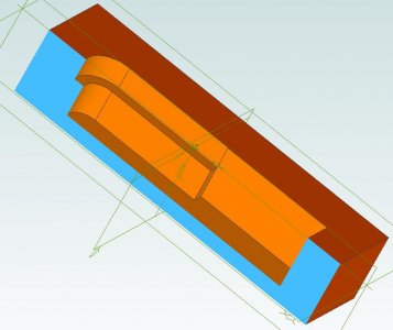
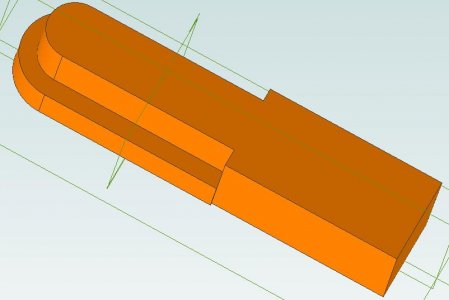
Meanwhile I found a paper by some Chinese PhDs on an alternative harmonic drive named HGD_EWG so I designed one using the two gear teeth parts from the first. It provides 36:1 and is quite large. Still needs some work. Instead of the wave generator on the inside it's now on the outside.

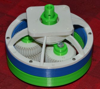
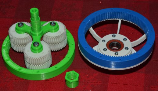
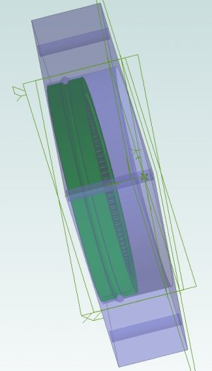
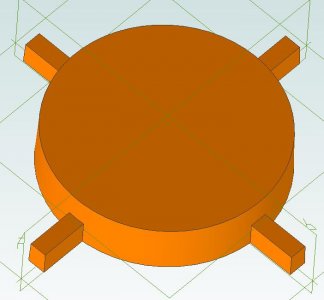
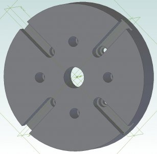
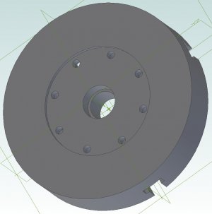
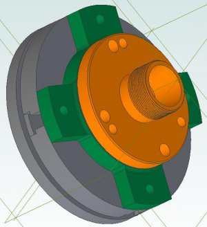
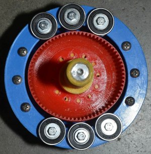
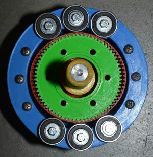
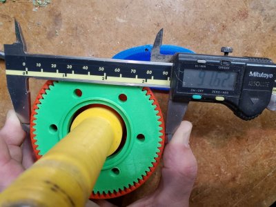
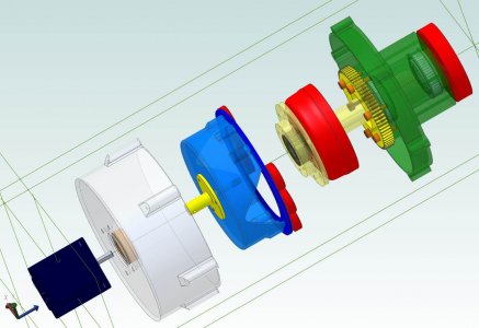
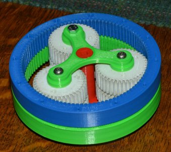
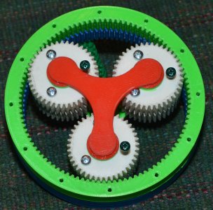
I am now distracted with a dual planetary (theoretically also zero backlash) system. It still needs mounting and a motor attached so it's still totally in an experimental stage. The initial drawings were done by Todd Zuercher on the LinuxCNC group in FreeCAD 0.19. I exported them as STEP files into Alibre and then took it from there to make 3D prints of his design. After some 'issues' we've come up with something that appears to work. Big thing about this is it uses standard involute gear profile and as long as one can make the inner ring gear there is no wearing out of a flex cup like a harmonic.

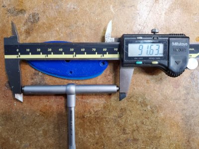
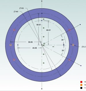
This one is designed with 1.25 module teeth and has 100:40 and 101:41 values for 67:1. The outer ring is 150mm in diameter.

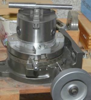
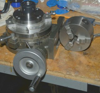
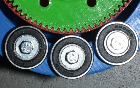
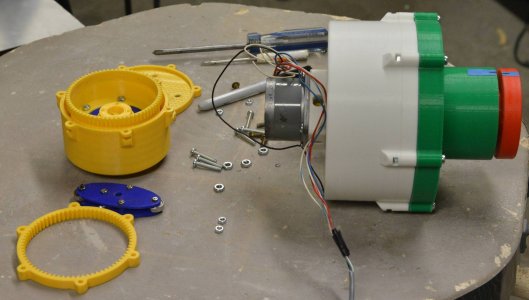
Needless to say the 3D printer has been busy as has the lathe boring out bearing holes for close fits.
 

Attachments

  • HarmonicDrive-28.jpg
    HarmonicDrive-28.jpg
    79.2 KB · Views: 11
  • HarmonicDrive-35.jpg
    HarmonicDrive-35.jpg
    217.1 KB · Views: 12
  • GearSide1.jpg
    GearSide1.jpg
    367.7 KB · Views: 11
  • GearSide3.jpg
    GearSide3.jpg
    378.8 KB · Views: 12

PeterT

Ultra Member
Premium Member
Cool. Do you mean you will ultimately replicate the 3DP gear assembly in metal? Reason I ask is I was going to make my own planetary gear train for my radial engine. The spur gears are made using regular gear cutters but the internal (ring) gear seemed quite a bit more involved from what I read. Not just the radial broaching action but some of the compensation features on the tooth form itself (depending on count, module etc.) I chickened out & bought them.
 

jcdammeyer

John
Premium Member
In the back of my mind I see building a large robot arm for the automatic tool changer. (and for fun). It's quite possible I can make the base joint out of plastic but the others need to be smaller. I have both 1.0 module and 0.5 module cutter sets. So project #42 is to built that bar that holds the cutter at the end with a shaft through it to a pulley on the other side which has a belt going back out to the drive motor. The cutter is set on center line and allows cutting inside gear teeth. As I understand it the last cutter in the set marked 135T to Infinity is used for making rack teeth so it's not really involute anymore. This makes the larger ring ring gear or cup gear pure triangles. An idea anyway.
 

Susquatch

Ultra Member
Administrator
Moderator
Premium Member
In the back of my mind I see building a large robot arm for the automatic tool changer. (and for fun). ........ An idea anyway.

My advice is to not ever try to make something you see in the back of your mind. While the vision center is indeed located at the back, it isn't organized in any way shape or form that would actually work in the real world. Unlike other parts of the mind, vision is not reversed right for left hemisphericly. However, it is reversed right for right and left for left and both are upside down. This is almost guaranteed not to work very well. My advice is to build what you see at the front of your mind after the back side version has been processed into something more usable.

PS - Don't blame me for any of the above. It's Saturday, the bride is driving me crazy, and the devil made me say it. ;)o_O:p
 

jcdammeyer

John
Premium Member
I’ve been watching this guy for a while he‘s made quite a few videos testing them.
Rather boring and a long sales pitch with very little information. I see from the previous video that likely you need to spend money to get the STL files and I doubt he'd distribute the actual physical drawings. Interesting ideas. Thanks for posting.
 

jcdammeyer

John
Premium Member
I have added a bearing holder and extended the planet holder to have a 19mm shaft diameter and 19x1.25mm threaded section. I also 3D printed the nut to hold the shaft firmly on the bearing. Now the planetary assembly won't slip out and keeps the planets centered. The end is 8mm for the stepper motor that arrived last week. Need to make an adapter to mount the motor to the frame.

Still no clear easy way to mount the front ring gear so it doesn't slip off. I can get a 130mm thrust bearing from AliExpress for about $30. But I think I'll have to create my own bearing for the radial positioning. The 5.5mm steel balls I got from the hobby shop would work if I made a groove and an outer frame to have them ride in. Would require 80 of the bearings.
 

Attachments

  • BearingDriveShaft-2.jpg
    BearingDriveShaft-2.jpg
    1.9 MB · Views: 3
  • BearingDriveShaft-1.jpg
    BearingDriveShaft-1.jpg
    1.6 MB · Views: 3
  • BearingPath.jpg
    BearingPath.jpg
    116.5 KB · Views: 3

jcdammeyer

John
Premium Member
The bearings from aliexpress arrived. I've put one into the harmonic drive case. That now shows the next step is to make some of the parts from metal. This includes the drive connection for the planetary sytstem. My New Years Eve had a couple of hours at the ER to check if I had a detached retina or just something else. Jan 1st (Saturday) had an appointment with an ophthalmologist (his door was marked closed from Dec 22 to Jan 4th for a more detailed exam. Turns out a floater that may go away in 3 months or so. Or not. So all I did was jig saw puzzles and a lot of CAD for the next while.

So harmonic drive and planetary gear projects are stalled until I can make some metal parts and I really must get the draw bar working and finished first.
 

Susquatch

Ultra Member
Administrator
Moderator
Premium Member
The bearings from aliexpress arrived. I've put one into the harmonic drive case. That now shows the next step is to make some of the parts from metal. This includes the drive connection for the planetary sytstem. My New Years Eve had a couple of hours at the ER to check if I had a detached retina or just something else. Jan 1st (Saturday) had an appointment with an ophthalmologist (his door was marked closed from Dec 22 to Jan 4th for a more detailed exam. Turns out a floater that may go away in 3 months or so. Or not. So all I did was jig saw puzzles and a lot of CAD for the next while.

So harmonic drive and planetary gear projects are stalled until I can make some metal parts and I really must get the draw bar working and finished first.

My new years eve was spent with Omicron.

Watch out about those big floaters. I went pretty much totally blind a few years ago. They said it was a detached retina. Had appointments with three ophthalmologists getting a diagnosis and 2nd opinion. The first 2nd opinion didn't seem to know he was 2nd so he referred my to a third 2nd opinion. The third guy said he thought it might be a retinal membrane that had not sloughed off properly with age. Scheduled a vitrectomy which confirmed his suspicion and he removed the membrane and replaced my vitreos fluid. 6 months later I needed cataract replacement surgery - which he predicted almost to the day.

15 years later, my left eye is doing the same thing but I can't get an appointment to fix it.

Just saying that I might be a floater or it might be your optic membrane. The first will dissolve away slowly. The second might pull your retina off your eyeball.

If you get flashes of light or pain in your eyes, pound on his door!
 

Tom O

Ultra Member
I’ve only had one floater it was really strange it blurred the right eye for a good half hour before it passed I’ve had no problems vision wise since.
 

jcdammeyer

John
Premium Member
Mine is a brown spot that tracks where my right eye points. Kind of interesting reading a book watching the spot track the words I'm reading. The worst part is it makes what I look at a bit out of focus. The Dr. said the same thing Susquatch stated which is call him if the flashes return or other things happen. So far they don't appear to be overly worried.

Meanwhile I'm 3D printing the two halves of a core form so I can cast the back plate with the majority of the T-Slot already there. The core form is in two halves so I don't have to make the T-Slot part of the core tapered. The square section is tapered to fit into the tapered part left by the pattern.

The idea is that the pattern leaves the 4 slots in the sand and the rectangular part of the sand cores are pressed into those slots. The T section is out in the empty part and should leave a rough T there that just needs simple cleanup. I hope. .....

Not sure whether I'll use ZA12 or 432 Silicon Aluminium. I have ingots for both.
 

Attachments

  • BackplatePatter.jpg
    BackplatePatter.jpg
    36 KB · Views: 1
  • T-Slot_CoreForm-RHS.jpg
    T-Slot_CoreForm-RHS.jpg
    47.4 KB · Views: 1
  • T-Slot_CoreShape.jpg
    T-Slot_CoreShape.jpg
    32.8 KB · Views: 1
  • ER32-ColleteAdaptorModel-1.jpg
    ER32-ColleteAdaptorModel-1.jpg
    170.3 KB · Views: 1
  • ER32-ColleteAdaptorModel-2.jpg
    ER32-ColleteAdaptorModel-2.jpg
    146.9 KB · Views: 1

jcdammeyer

John
Premium Member
Oh and just to add to this since it is a harmonic drive thread. I did buy a real harmonic drive for the 4th axis. I don't remember if I posted this link to the story:

I need to expand on this to talk about the ER32 Collet Chuck and Collet Set I bought and that's what this face plate is all about. The green adaptor that bolts to the face plate of the harmonic drive or my manual rotary table has been cast for a 3Jaw chuck using a pattern given (loaned) to my by the late Rupert Wenig in Camrose. I can't find it so I must have given it back the last time I visited him. But as the photo shows the collet chuck fits perfectly so it seemed the best way to go to allow either to be mounted to the rotary axis.
 

Attachments

  • ER32-ColletAssembly.jpg
    ER32-ColletAssembly.jpg
    41.3 KB · Views: 2
  • 3Jaw_Adaptor.jpg
    3Jaw_Adaptor.jpg
    194.6 KB · Views: 2
  • ER32-Collet.jpg
    ER32-Collet.jpg
    180.6 KB · Views: 2

Susquatch

Ultra Member
Administrator
Moderator
Premium Member
Oh and just to add to this since it is a harmonic drive thread. I did buy a real harmonic drive for the 4th axis. I don't remember if I posted this link to the story:

I need to expand on this to talk about the ER32 Collet Chuck and Collet Set I bought and that's what this face plate is all about. The green adaptor that bolts to the face plate of the harmonic drive or my manual rotary table has been cast for a 3Jaw chuck using a pattern given (loaned) to my by the late Rupert Wenig in Camrose. I can't find it so I must have given it back the last time I visited him. But as the photo shows the collet chuck fits perfectly so it seemed the best way to go to allow either to be mounted to the rotary axis.

That is really cool stuff. Very well done!
 

jcdammeyer

John
Premium Member
Drawbar project postponed due to frustration. So even though it probably isn't necessary I decided to use cores to cast the back plate. One for the center to avoid drilling out and wasting metal since chips don't turn back into castings very well. Plus just because I can...

Anyway, since I don't have CO2 and I haven't been able to dissolve desiccant granules into liquid anyway I went back to the Dave Gingery recipe I used for the Lathe Tailstock bore. Did some testing with ratios. Went a bit overboard with not enough strength although I might still have to use a carbide tip masonary drill to remove the cores. We'll see.

The pattern isn't done yet. But now at least I have the cores done. The 5/8" core section is the same core box and support I used to make the core for the Gingery Lathe. (Never throw anything out).

Since I don't have a fume hood above the foundry furnace I still need to do this outside. Weather permitting. Might be a few days before I cast anything and I might just try a small block with one of the T-Slot cores first to see how easily it can be broke out. And for that matter the machining afterwards.

More when that happens.
 

Attachments

  • TSlot-Cores.jpg
    TSlot-Cores.jpg
    310.5 KB · Views: 3
  • Core0.625.jpg
    Core0.625.jpg
    296.4 KB · Views: 3
  • FirstCore.jpg
    FirstCore.jpg
    96.5 KB · Views: 3
  • TSlot-CoreBox.jpg
    TSlot-CoreBox.jpg
    111.8 KB · Views: 3

jcdammeyer

John
Premium Member
Here's the 4 of them and the core arranged how they will be in the flask. The aluminum plate represents the face of the casting and the tapered rectangular sections stick out into the recesses made by the pattern. The T-Slot sections create the rough slots in the casting.

Oh and the different colours are due to me adding a bit more molasses liquid so the T-Slots wouldn't fall apart as easily as I separated the core box. The oven was also already hot when they went in so perhaps overheated a bit; 350F, 30min.
 

Attachments

  • TSlot-Configuration.jpg
    TSlot-Configuration.jpg
    297.3 KB · Views: 3

jcdammeyer

John
Premium Member
I've done a bit more work on the harmonic drive with external wave generator. After playing with a spreadsheet to calculate ellipses and measuring 'as printed' items I came up with a new mount ring and internal bearing. I also used the Alibre CAD Python script to actually design the M1.25 gears instead of cutting and pasting and trimming the original internal wave generator gears.

The photos show the results. I'm still having fatique issues with the 3D printed PLA cup bearing so next step is to print one from PETG which is more flexible.

Major next step is to machine (out of metal) the coupler to the stepper motor. I've found the plastic just doesn't really do it well enough.

In either case though the photos show that without the center gear the cup gear takes an elliptical shape but is a bit stiff and doesn't quite touch the middle bearing. With the gear installed roughly the same contact force on all the bearings and the closeup shows the teeth do not bottom out.

Dimension between the center bearings matches the gear+cup dimension. And 45.85x2=91.7mm so only a bit of shrinkage from the 3D print which is 91.63. Close enough for Jazz.
 

Attachments

  • CenterBearingGap.jpg
    CenterBearingGap.jpg
    209.7 KB · Views: 2
  • ToothEngagement-2.jpg
    ToothEngagement-2.jpg
    313.4 KB · Views: 2
  • ToothEngagement.jpg
    ToothEngagement.jpg
    320.5 KB · Views: 2
  • ToothEngagement-1.jpg
    ToothEngagement-1.jpg
    222.2 KB · Views: 2
  • MountRingDimensions.jpg
    MountRingDimensions.jpg
    71.1 KB · Views: 2
  • GearClusterWidthjpg.jpg
    GearClusterWidthjpg.jpg
    166.8 KB · Views: 2
Last edited:

jcdammeyer

John
Premium Member
Oh and over tightening a plastic nut on a plastic shaft is never a good idea. Especially since the tapered roller bearings would be too tight anyway doing that. So I accidentally broke it.

Broken.jpg

Fortunately it was hollow (don't remember why I designed it that way but it means I could insert something to fix it. in this case a piece of cast aluminum sprue turned down to the right diameter. Then I used the lathe tool bit as a shaper to create some grooves.

MainShaftRepair.jpg

Some 5 minute epoxy and a while later it was back to normal.

MainShaftRepaired.jpg

Once the glue had fully cured I mounted it in the lathe and the supported the outboard end in the tailstock. Then with the parting tool cut a thread run out area so the threads on the drive disk wouldn't run into the unthreaded part which is what I think also contributed to it breaking. The unthreaded part stuck out above the bearing a teensy bit. Enough that I was probably jamming the nut against the un threaded part rather than the bearing.
ThreadRunout.jpg

Now I can tighten the hub and feel the tapered roller bearings get way too tight. Baby steps here.
 

jcdammeyer

John
Premium Member
Bit of an update here. Printing a PETG cup resulted in damaging my printer so that took a while to sort out. It's now printing a new cup with some changes. I had always thought that the inadequate contact was because the ring holding the bearings was twisted away by the force to bend the cup. In the photo you can also see a line imprinted into the cup by the edge of the bearing.
PoorBearingContact.jpg

I did some measuring and found that the diameter at that point was larger than the diameter at the top. What's up with that I wondered? I pulled out some measuring tools and it looked to be out by about 2 degrees. (roughly).

Back to the CAD system to see if I could duplicate the mechanical measurement. And sure enough I did.
The outer cup has 72 M1.25 teeth while the inside gear has 70T. That results of course in the cup having a larger diameter. The bearings push the cup in at the sides creating an ellipse forcing the cup 90 degrees away from the pressure point to bow out into an ellipse shape. The bearings are mounted on that ellipse path at the narrow section of the ellipse.

However, as the vertical line shows, to press the cup inwards to the point where mates completely with the cup (from radius 47.25mm to 45.85m), results in a 2.5 degree angle. And that's why the bearing is only touching at the bottom. The pivot point might not be the exact point where the cup bends but close enough to real life.
VerticalSides.jpg

So the thing to do is to redraw the cup so it has a 2.5 degree outwards taper that results in the edge sitting vertical when the cup is pressed in and the teeth are full meshed.
TaperedSides.jpg

I haven't figured out how to create a tapered ring gear in CAD so instead I just did a tapered cut on the inside but that shaved too much off the tooth root. Slicing the drawing for printing showed holes between the teeth. So I widened the top of the cup by 0.65mm which means 13mm down the root of the gear would still be 1mm and align with the body of the cup. That's now visible in this shot.

CupThickening.jpg

The next shot shows how the tooth bevel and root merge into the inside of the cup and that the depth is about 1mm. CupThicknessBottomTooth.jpg

Busy printing now. Will need to make a new bearing holder ring with the bearings moved out to compensate for the 2 x 0.65mm thickness at the top. Here's a screen grab from the Raspberry Pi2 camera and Octopi screen.
1647989769665.png
 

jcdammeyer

John
Premium Member
Now printing the new bearing carrier.
It's quite the exercise to determine the 28mm OD bearing positions.
First of course do a trial fit and it's pretty close to the expected 93mm remembering of course that the ring shrinks a bit and the bearings will be closer to 92.7mm from bearing OD to OD.
TrialFitTaperedCup.jpg

The CAD system lets me define an ellipse with the a,b dimensions. The OD of the fixed 70T gear and the thickness from cup gear to outside calculate to be 93mm (46.5 radius) and holding the cup compressed against the inner gear. As the above photo shows, pretty darn close.

The OD of the cup gear when not squished from the CAD drawing is 96mm and that results in a circumference of 301.6mm which with the ellipse formula means the peak of the ellipse radius should be 49.45.

Add the 14mm bearing radius to the small one to get 60.5mm for the small radius of the ellipse. Placing a second ellipse with the long radius calculated from 60.5mm is 63.31mm.

Now place a 4.3mm hole on the X axis on the second ellipse and a second one 28mm up also on the second ellipse. Now mirror across X and then again across Y to create all 6 bearing holes.
TaperedCupBearingMount.jpg

Now save and export as stl and import into Repetier to create G-Code and wait 2.7 hours for print to finish.

Hopefully I haven't made any mistakes and the bearings will be a sliding fit over the cup this time with a flat bearing to cup fit.
 
Top