• Spring 2024 meetup in Calgary - date Saturday, April 20/2024. discussion Please RSVP Here to confirm and get your invitation and the location details. RSVP NOW so organizers can plan to get sufficient food etc. It's Tomorrow Saturday! you can still RSVP until I stop checking my phone tomorrow More info and agenda
  • We are having email/registration problems again. Diagnosis is underway. New users sorry if you are having trouble getting registered. We are exploring different options to get registered. Contact the forum via another member or on facebook if you're stuck. Update -> we think it is fixed. Let us know if not.
  • Spring meet up in Ontario, April 6/2024. NEW LOCATION See Post #31 Discussion AND THE NEW LOCATION

HAAS CNC file.

jcdammeyer

John
Premium Member
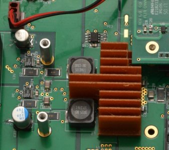
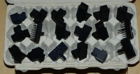
The CNC shop that used to make my heat sink has closed down. I think I've mentioned that before. He's kept a HAAS and some other equipment for playing with motorcycles. After whining and snivelling and supply some extra raw material he made 40 of them for me. Got to watch some of them being made. Very educational.

1710999157688.png
When I picked them up he also gave me the Niagara 3 flute 1/8" end mill he used to make the fins along with a lesson on how he did the chamfering on the fin edges. A shame to see all the knowledge retire.

He also gave me a zip drive with the top and bottom machining information in the form of two VNC files. The first part is text but the rest is binary. Is there a way to turn these files into G-Code or are they HAAS only?

I'm off to Vancouver tomorrow to have them anodized.
 

jcdammeyer

John
Premium Member
I've had some success. Using a FADAL Post Processing file acquired from the CNC Zone group and a 30 day trial of the GibbsCAM I've generated G-Code along with a table of the tools and the speed+depths for each path.

1711591220180.png

I think I would be very afraid to spin 10,000 RPM and 30 IPM while cutting with a 1/8" 3 flute end mill although it looks like depth per pass is only 0.045" with flood coolant.

1711591459886.png
 

jcdammeyer

John
Premium Member
Seems like a very basic G-Code file to me with an Excel spreadsheet for operation information.
The spreadsheet is exported to have a record of what is in the program. I have subsequently figured out how to change parameters and instead of the FADAL output I've been able to use a LinuxCnc-Mill-jk.pM3 as the configuration information for a PosteHaste Plugin. Changing the spreadsheet entries for spindle speed and feed rate does work but that's the correct way to set this up.
For each tool path operation I can set spindle speed, feed rate for entry/exit so I went through that list and divided the speeds by 4 since I don't have a 10,000 RPM spindle but can nicely do 2750 and with that reduced speed I cut the feed from 60 or 30 down to 15 or 7.5. Then ran the G-Code generation again.\

% ; Prog # 2 G90 G80 G40 G17 (TOOL 2) (OPERATION 1) ; *** First Tool change *** T2 M6 S2750 M3 G0 X1.725 Y0.14 G43 Z0.5 H2 M8 G0 Z0.32 G1 Z0.2233 F15.0 X0.81 Y-0.625 ...

The pM3 file documents that the G43 has a Z and H2 where H2 means use the tool offset. But then the G43 does that automatically on the LinuxCNC system. So I'm not sure why that is happening so more research is required.

To set up a particular path the GibbsCAM has this set of operations.
1711645092494.png

And the tool path the above form is describing is this one.
1711645309539.png

I believe all the machinist had to draw was the two straight lines. The blue is the result of the cutting operation. Not sure what all the other circles are about. Probably really should spend some time reading the manual.

All for now. Must walk doggy.
 

jcdammeyer

John
Premium Member
Quick update. Got a call from https://westcam.com/ today. Spoke with Chuck Van VolkingBurgh. Nice guy. They target the high end big machine shops. They will create a specific custom .pst file for a price. If I was running a large CNC shop I'd definitely consider them since that GibbsCAM system seems to be well supported.

However, just like Fusion 360 it doesn't press my buttons but then way back I really didn't like Autocad either.


lucsimoneau

Active Member
Can't go wrong with Fusion 360 - I've been teaching/reselling Mastercam for the past 30 years but for a hobby shop it's just too expensive. Fusion 360 is free (or very low cost) and provides tons of free post-processors and also has parametric design features. Just my 2%
 

PeterT

Ultra Member
Premium Member
I've been teaching/reselling Mastercam for the past 30 years
Not that I'm in the market or even remotely knowledgeable about CNC, but would you say Mastercam is usually associated with shops using SolidWorks for CAD, or do they tend to a different package for specific reasons?
 

jcdammeyer

John
Premium Member
From my CNC perspective the worst thing that happened is Mecsoft VisualCAM plugin for AlIbreCAD (AlibreCAM) being discontinued.
VisualCAD is a piece of junk compared to AlibreCAD.

I have tried a number of other CAD packages and none of them click for me.
It's like when Protel99 pcb software became Altium. Better but harder to use. Even though I have the newer Altium I'll still do a board in Protel.
 

lucsimoneau

Active Member
Mastercam is not tied into any CAD software specifically, but there is a Mastercam for SolidWorks option available for SW users. I could on and on but if just answering your question this would be it. Mastercam has a very extensive reseller network that provides training, post customization and services. CNC Software, which since the beginning was a family owned business, has been acquired by Sandvik.
 

jcdammeyer

John
Premium Member
The trend has gone in the direction of working with step files rather than with original cad files. So yes, I can export a step file and use it in just about any CAM system. What made the Alibre system so attractive is the CAM was launched from within the CAD. To select a path for a tool to follow I could either select edges inside the CAM window or flip to the CAD side and select a specific sketch that might have 15 lines. Since often the step files export circles as two half circles it requires two selections.
Also with the step file approach after spending say an hour on setting up the CAM you decide you need a tiny change to the drawing to make it more machinable. No problem. Into the CAD system. Export as step file. Import into CAM and start all over again.

For example: The GibbsCAM model showed a path around the fins before they were created so the .125" end mill wouldn't have to remove much on entry and exit into each slot. So I went back into the CAD system.v I drew the blue line around the edges of the fins as a sketch.

1711745432960.png

Then back to the CAM and create a outer profile operation using a .25" end mill just like the GibbsCAM. Instead of a whole bunch of lines the sketch.

1711744797881.png

However for the fins as they are separate sketches it did turn into a lot of lines. The GibbbsCAM operation was done exactly the same way.

1711745474171.png

Which still results, after choosing entry and exit points results in the initial top slots.
Hope that makes sense. And just as a side note. There are instances where editing the drawing and then returning to the CAM erases all the selected lines and you do have to start over. But the tool, feeds and speeds etc. remain so it's not a total start over.

1711745679742.png
 
Last edited:

Janger

(John)
Administrator
Vendor
Interesting project. I wondered how industry makes heat sinks. Milling is not very efficient. The fins on some heat sinks are very tall and very thin perhaps 0.5mm or even 0.2mm thin. Are those milled too? For larger numbers of heat sinks would they be cast? John would you cast them?
 

jcdammeyer

John
Premium Member
Interesting project. I wondered how industry makes heat sinks. Milling is not very efficient. The fins on some heat sinks are very tall and very thin perhaps 0.5mm or even 0.2mm thin. Are those milled too? For larger numbers of heat sinks would they be cast? John would you cast them?
They are generally extruded through a die. In fact the first prototype was cut from an old PC CPU heat sink.
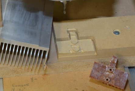
First modelled with 3D printer and trial fit.
HeatSinkInPlace.jpg
and a trial cut done in MDF. Used my JGRO CNC router with MACH3 to do that as the mill wasn't totally CNC yet.
TrialRun1.jpg
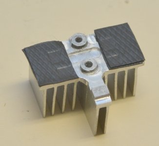
Then cut from the extrusion and fit with heat conductive pads.
Pads4Fets.jpg
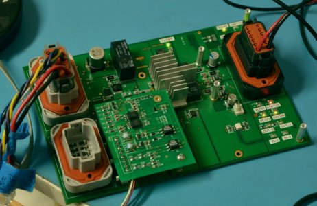
Finally also a trial ft on the board.
NoPads2Fets.jpg
Testing then done to ensure that it carried the heat away at full power inside the enclosure. It did. I looked at getting extrusions as raw material. But ultimately with everything that was going on it was easier to contract out the fabrication.
CommercialHeatsinks.jpg
These are cut in a number of stages. First the outline and then top 3mm or so of fins are cut in multiple passes. Then the chamfer tool is run around the edges of the top of the fins as they are still short and don't vibrate. The gap is also wider than it will be further down since the end mill doesn't have cutting edges for the entire length. Then the unit is flipped over in the vise and the rest of the bottom is milled and the two holes are tapped.
 
Top