• Scam Alert. Members are reminded to NOT send money to buy anything. Don't buy things remote and have it shipped - go get it yourself, pay in person, and take your equipment with you. Scammers have burned people on this forum. Urgency, secrecy, excuses, selling for friend, newish members, FUD, are RED FLAGS. A video conference call is not adequate assurance. Face to face interactions are required. Please report suspicions to the forum admins. Stay Safe - anyone can get scammed.

Figuring out radius differences

DPittman

Ultra Member
Premium Member
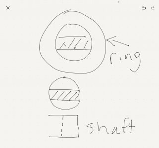
Forgive my lack of CAD or any resemblance or talent regarding a drawing but that's all I can do.

I'm trying to mill a blind slot in an aluminum pulley for the end of a motor shaft to fit in.

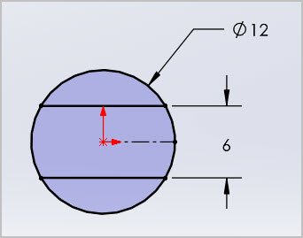
The shaft started out as a 12mm diameter but was milled on two sides to make a 6mm wide "bar" but with 12mm radius ends. (This was factory done on an electric die grinder).

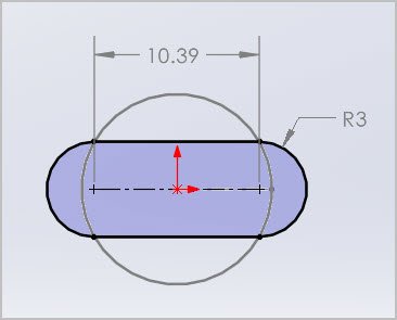
I milled the slot in the aluminum using a 6mm end mill but of course ended up with 6mm radius ends instead of 12mm.

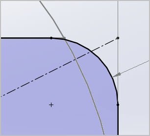
Is there some redneck math/way I could figure out how to mill the end corners a bit more to get the shaft to fit? I don't really want to overshoot the slot length a whole bunch past the right length but I guess that might be one way.
I'm guessing if there is a way it's probably above my pay grade but I thought I would ask just in case. 16500417720156125778181114578971.jpg 165004179073626685217120418173.jpg
 

Darren

Ultra Member
Premium Member
your shaft has a 6mm radius, and your 6mm endmill is producing a 3mm radius, unless geometry has recently changed.

You'd hafta use a rotary table and a small endmill to produce it, or broach it, or just make the slot longer as necessary to fit.
 

PeterT

Ultra Member
Premium Member
That's a tricky one depending on what you want to fit & why and machining effort &tooling on hand. I don't think the ends of the profile cutout add anything in terms of driving the pulley, but maybe there are other reasons you want it to fit. Anyways here are some images, maybe will help you visualize closer.
- a plain slot will fit the 6mm keyway but you give up any contact to 12mm shaft
- a pocket milled rectangle might work but geometrically has radius interference contact, but maybe within acceptable limits if you round over the corner edge between flat & shaft OD? (but it only really contacts the shaft OD at the tangent, so fills the gap a bit but not doing anything mechanically)
- 4 relief holes on the corners, this allows making the 2 lines & 2 arcs at the expense of a little bit of contact area (need to be selective about relief hole dia & EM dia)
 

Attachments

  • SNAG-2022-04-15 11.23.19 AM.jpg
    SNAG-2022-04-15 11.23.19 AM.jpg
    13.4 KB · Views: 1
  • SNAG-2022-04-15 11.25.58 AM.jpg
    SNAG-2022-04-15 11.25.58 AM.jpg
    14.4 KB · Views: 1
  • SNAG-2022-04-15 11.29.04 AM.jpg
    SNAG-2022-04-15 11.29.04 AM.jpg
    25 KB · Views: 1
  • SNAG-2022-04-15 11.29.15 AM.jpg
    SNAG-2022-04-15 11.29.15 AM.jpg
    10.8 KB · Views: 1
  • SNAG-2022-04-15 11.31.18 AM.jpg
    SNAG-2022-04-15 11.31.18 AM.jpg
    18.4 KB · Views: 1

Darren

Ultra Member
Premium Member
That's a tricky one depending on what you want to fit & why and machining effort &tooling on hand. I don't think the ends of the profile cutout add anything in terms of driving the pulley, but maybe there are other reasons you want it to fit. Anyways here are some images, maybe will help you visualize closer.
- a plain slot will fit the 6mm keyway but you give up any contact to 12mm shaft
- a pocket milled rectangle might work but geometrically has radius interference contact, but maybe within acceptable limits if you round over the corner edge between flat & shaft OD? (but it only really contacts the shaft OD at the tangent, so fills the gap a bit but not doing anything mechanically)
- 4 relief holes on the corners, this allows making the 2 lines & 2 arcs at the expense of a little bit of contact area
relieving the corners might be the easiest way to get a tight fit with minimal effort.

I knew you'd be along with your fancy drawings. Wish I had your skills!
 

DPittman

Ultra Member
Premium Member
Do you have a RT?
Oh of course that would have worked! Maybe on version 2 of this thing as I am still figuring out what I'm doing (obviously)

I put in a 4mm end mill and took out a bit in the corners, it sort of worked. The first slot milling attempt I miscalculated and made the slot way too long so I filled it jb weld and milled another one 90 degrees to it. It usually takes me 2-3 tries before I ever get anything right. 16500445176666969418964911422660.jpg
 

PeterT

Ultra Member
Premium Member
oh, duh. The slot wont work. The pulley has to make contact with shaft OD in order to center. Scratch that sketch
 

Attachments

  • SNAG-2022-04-15 11.44.17 AM.jpg
    SNAG-2022-04-15 11.44.17 AM.jpg
    11.3 KB · Views: 1

DPittman

Ultra Member
Premium Member
That's a tricky one depending on what you want to fit & why and machining effort &tooling on hand. I don't think the ends of the profile cutout add anything in terms of driving the pulley, but maybe there are other reasons you want it to fit. Anyways here are some images, maybe will help you visualize closer.
- a plain slot will fit the 6mm keyway but you give up any contact to 12mm shaft
- a pocket milled rectangle might work but geometrically has radius interference contact, but maybe within acceptable limits if you round over the corner edge between flat & shaft OD? (but it only really contacts the shaft OD at the tangent, so fills the gap a bit but not doing anything mechanically)
- 4 relief holes on the corners, this allows making the 2 lines & 2 arcs at the expense of a little bit of contact area (need to be selective about relief hole dia & EM dia)
My gosh man you are fast with technical drawings! Thats hilarious and awesome at the same time.
 

RobinHood

Ultra Member
Premium Member
In version 2.0 you could bore the pulley to the motor shaft diameter (12mm). Then insert “wedges” on either side where the flats are. The wedges can be locktighted in (and pinned if required).

The wedges are made from stock turned to 12mm and then a slot milled through the Center. The width of the slot is equal to the distance across the flats on the motor shaft. After the slot is cut, stick the stock back into the lathe and part the wedges off to length.

I did a similar process (only one wedge) when I needed to make an internal “D” drive in a gear.

17ABD04C-FED1-4858-BD08-75F7630BCA7B.jpeg
 

Mcgyver

Ultra Member
just grab for for the tool makers best friend or the red neck end mill....otherwise known as a file :D


jk90mEa.jpg
 

whydontu

I Tried, It Broke
Premium Member
i have probably made a thousand double-d shaft adapters. Turn a stub to 12mm o.d.. Cut a 6mm slot across the end of the stub shaft. Turn a ring to 12mm i.d. Slide the ring over the slotted 12mm stub. A couple of tack welds to hold them together, or drill and tap for a setscrew.

You have enough clearance in the bearing housing to make a pretty beefy ring.
 

Attachments

  • 941E07E8-7577-4B3A-BB68-661019B1E70D.jpeg
    941E07E8-7577-4B3A-BB68-661019B1E70D.jpeg
    216.6 KB · Views: 2
Last edited:

DPittman

Ultra Member
Premium Member
Awesome suggestions. The slot I need to make is a blind hole so filing it to shape and dimension is not an option but the other methods sound like they could all be feasible.

I do not want to put in a set screw on the flats as there will be no clearance for that (at least in present "plans") and I want to keep the pulley as balanced as I can as it will be spinning up to 30000 rpm.
 

Mcgyver

Ultra Member
lol, yeah you need speial files for blind holes (j/j). My bad not reading more thoroughly. I done similar what I thnk Robin is describing, make sort of an insert by turning milling and even soldering bits together
 

YYCHM

(Craig)
Premium Member
I actually don't have a rt but I have a dividing head and think I could accomplish this on that possibly

My thinking was mount the piece vertically on the RT and mill out the larger arc with a narrow endmill?
 

DPittman

Ultra Member
Premium Member
My thinking was mount the piece vertically on the RT and mill out the larger arc with a narrow endmill?
Yup that makes sense and i think I could accomplish that with my dividing head also. I think I will use that as plan C, I'm going to attempt plan B which is RobinHoods' milled wedges from above.
 

DPittman

Ultra Member
Premium Member
Wel I think I made improvements with V2 imploying the techniques @RobinHood
suggested.

I milled out a slot in correct size shaft and then cut off those pieces and used Loctite to hole them in place in a milled out hole in the pulley blank.

I turned down the final dimensions and profile of the pulley once it was attached to armature to hopefully gain some improved balancing. 20220417_142626.jpg 20220417_155814.jpg 20220416_103612.jpg 20220416_122051.jpg
 
Top