• Spring 2024 meetup in Calgary - date Saturday, April 20/2024. discussion Please RSVP Here to confirm and get your invitation and the location details. RSVP NOW so organizers can plan to get sufficient food etc. One week to go! More info and agenda
  • We are having email/registration problems again. Diagnosis is underway. New users sorry if you are having trouble getting registered. We are exploring different options to get registered. Contact the forum via another member or on facebook if you're stuck. Update -> we think it is fixed. Let us know if not.
  • Spring meet up in Ontario, April 6/2024. NEW LOCATION See Post #31 Discussion AND THE NEW LOCATION

Extruder heater failure?

jcdammeyer

John
Premium Member
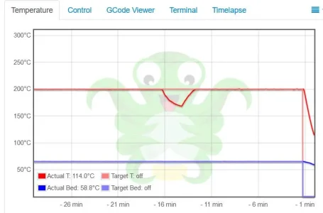
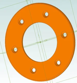
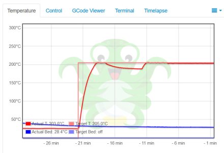
I printed a small part and noticed this blip. I also realized I'd forgotten to change the diameter of mounting holes from 64mm to 60mm so I had to print it again. And there was the same blip. It's a 50 minute print. Blip happened at about the same time. There's nothing in the G-Code that touches the extruder temperature.

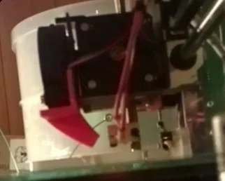
I think I'll just replace the heater but it's strange.
 

Attachments

  • TopCoverBearingRetainer.jpg
    TopCoverBearingRetainer.jpg
    49.7 KB · Views: 4
  • HeaterFailure.jpg
    HeaterFailure.jpg
    29.5 KB · Views: 4

jcdammeyer

John
Premium Member
So I've replaced the hot end heater. All nicely put back together. Ran a small 18 minute print and sure enough the temperature dropped.
Next ran the 40 minute one and once again the dip happened near the end of the print.
Here's the dip to about 175C.
TemperatureBlip-1.jpg

As the dip started downwards I captured what was printing.
TemperatureBlip-2.jpg

Just before the extruder returned to and reached original temperature I captured the layer again.
TemperatureBlip-3.jpg

There's nothing to suggest the filament is extruding too fast and the heater can't keep up. It's odd that it's showing up at pretty well the same point in time. Or for a small 18 minute print way earlier than the 40 minute print.

Any suggestions as to why this is happening?

Nothing in the G-Code. There are two fans blowing on the CPU board keeping the drivers more than cool enough. My reflective laser temperature sensor doesn't report any abnormalities.

I guess next I'll have to put a scope on the extruder heater drive output to see if it's pretending to be on or somehow doing PWM when it shouldn't.

Very confusing. Never had it happen before.

Thanks
John
 

Janger

(John)
Administrator
Vendor
That is weird. Are the prints affected? Does the temp actually drop or is it a measurement problem?
 

jcdammeyer

John
Premium Member
I now know why the temperature is dropping. I'm not sure why it suddenly started but I do have an idea.

This is a small 18 minute print. I had set the temperature to 205C and 70C and when it stabilized I started the print.
1. First layer printed at 205C and 70C.
2. Temperature drops to 200C and 65C for subsequent layers.
3. After 3rd layer or under a certain level size the auto-cooling rules take effect and the external head mounted cooling fan kicks in at rates between 30% and 100%
4. Element can no longer keep temperature at 200C until I unplug the external fan.
5. Temperature remains stable for the rest of the print.

TemperatureBlip-6.jpg

I honestly can't remember if I've seen the fan spinning in the past. With all the work rewiring the fan, heater and sensor I might well have plugged in or mechanically re-installed that fan so that it now started working.

Or, the replacement (now ball bearing) extruder fan that runs continuously is way more efficient and the airflow past the heat sink down towards the bed now cools the extruder body and top layer of the print. Add external fan and now the heating element can't keep up.

Power supply is steady at 11.99VDC +/-400mV. The variation of the supply voltage (monitored with a scope) while printing doesn't show enough of a dip or sag under load that would cause the heating element to drop.

One potential solution is to bump up the power supply by a volt or so to add some reserve capacity to the extruder heater.
 

Janger

(John)
Administrator
Vendor
Hey John,
In the prusa slicer there are settings you can adjust to turn down or turn off the fans. That translates into G or M commands in the gcode. Not sure what slicer you are using but I believe the prusa slicer should work if you configure it for your printer and canned setups for other than prusa printers are included. Are you in the Calgary area? I could try printing your part as another test for you.
 

jcdammeyer

John
Premium Member
Hey John,
In the prusa slicer there are settings you can adjust to turn down or turn off the fans. That translates into G or M commands in the gcode. Not sure what slicer you are using but I believe the prusa slicer should work if you configure it for your printer and canned setups for other than prusa printers are included. Are you in the Calgary area? I could try printing your part as another test for you.
Hi John,
I'm in Victoria. The Slic3r software can dynamically adjust the outside blower fan or I can control it manually. This photo is of the RHS of the head assembly. The printed duct really blows on both the extruder heater block and the print. It's poorly implimented so I think I'll change it.

I'll photograph the other side. That has the small 40mm fan blowing onto a heat sink which is bolted to the bottom block that holds the threaded feed pipe with the teflon insert. which holds the heater block and nozzle. The air from this fan can go up and down so some of it already blows on the print and bed.

All this started when that fan failed which resulted in the overheated block and frozen plastic. I had 25 of these fans in stock for a product I make and it's a much higher quality ball bearing unit. I think it blows harder and cools better. I'm not sure it's PWM speed controlled though. Have to look into that.

John
 

Attachments

  • TemperatureBlip-4.jpg
    TemperatureBlip-4.jpg
    8.5 KB · Views: 2

jcdammeyer

John
Premium Member
When you look at that photo and see how the air from the front fan is ducted down to the build plate you can see how much of it is actually blowing on the hot end. Add the air that cools the heatsink also blows down and some may collide against the hot end causing additional cooling and also layer cooling.

Looking at all the different fan+duct solutions available now, say compared to 6 years ago, like this set, it's clear that my printer could be dramatically improved just by changing the duct work. It's quite possible that over the years, I either accidentally jammed or had the bed fan disconnected. Which is why I've never seen the temperature fluctuations.

The other photo was done with the RPi2 Camera while this one with my LG Phone. I think at a minimum I need to redesign the red duct.
ExtruderWithCooling.jpg
 
Last edited:

jcdammeyer

John
Premium Member
So for anyone who wants a peek here's the STP file that I've created by measuring the original. Need to take doggy for a walk but when I get back I'll do some measuring on the machine and change the duct section to blow lower down more like the more modern systems.

PlateFanDuct_Part.jpg
 

Attachments

  • PlateFanDuct.zip
    17.6 KB · Views: 0

Johnwa

Ultra Member
You could rotate the heater block so it is on the other side of the nozzle. There are also silicone heater block covers that should help.
 

jcdammeyer

John
Premium Member
You could rotate the heater block so it is on the other side of the nozzle. There are also silicone heater block covers that should help.
Thanks. I spotted those in one of the videos. I'll have to look into where to buy one. That can't hurt no matter what. Right now I'm printing an updated nozzle assembly which spreads the air out lower down and over a wider path. I imagine just that and the silicone will probably make all the difference in the world.
 

jcdammeyer

John
Premium Member
Going to have to print another one of these. This works much better. The chart shows rise to temperature. Then held with fan off. With fan 100% temperature drops 15 degrees. Set fan to 25% and it holds at set point. Set fan at 50% and it drops 1.5 degrees.
NewCoolerTemperature-1.jpg
But the bigger problem is I didn't take into account the spring clips holding the glass plate. So I need to redo this so the profile is more like the pencil line.
ExtruderWithNewCooling.jpg

Back to the drawing board. Each vent takes just over an hour to print.
 
I seem to recall reading about similar problems about 10-15yrs ago) when researching DYI reflow ovens for surface mount. A lot has to to do with the temperature controller and its response time, consider looking into that issue. This in conjunction with the heating elements response time causes delays and fluctuations. My understanding is that you need to hit that balance between too cold and too hot in the programming and compensate for the drift and varation.
 

jcdammeyer

John
Premium Member
I seem to recall reading about similar problems about 10-15yrs ago) when researching DYI reflow ovens for surface mount. A lot has to to do with the temperature controller and its response time, consider looking into that issue. This in conjunction with the heating elements response time causes delays and fluctuations. My understanding is that you need to hit that balance between too cold and too hot in the programming and compensate for the drift and varation.
Thanks.
Internet searches on this problem did bring up that as an issue. However, I don't remember ever seeing this problem before I damaged the nozzle assembly with too high a heat because the fan failed.

Scope shows steady DC supply. Only when the external filament cooling fan is above 50% can the heater no longer maintain temperature. If it were a control issue why now? Replacing both heater and thermistor did not make a difference. The curve shows tiny fluctuations as if either it's holding it there or just can't warm it up past a certain point when there's air blowing across the nozzle.

I've redesigned the blower. One more try and printing the latest version and then I'll pull a bunch of stuff so I can get a sensor wire in to the actually heater power output and put the scope on that. If it cycles while at the slightly lower temperature then it has to be the control loop. If it's on all the time then perhaps it's time to bump the power supply up from 12V to 13V.

The attached screen shot shows what happens when the fan is switched on to 100% near the build plate. What happens when the fan is dropped to 50% and then when the extruder is moved 10mm above and fan back to 100%.
 

Attachments

  • NewCoolerTemperature-1.jpg
    NewCoolerTemperature-1.jpg
    63.3 KB · Views: 0
Last edited:

Johnwa

Ultra Member
Thanks. I spotted those in one of the videos. I'll have to look into where to buy one. That can't hurt no matter what. Right now I'm printing an updated nozzle assembly which spreads the air out lower down and over a wider path. I imagine just that and the silicone will probably make all the difference in the world.
Here’s a link to a silicone heater block cover.


jcdammeyer

John
Premium Member
So this is a "do not try this at home" posting. For a test I wrapped some fibreglass around the feed tube which also covered the top of the hot end. One mustn't do this for too long or the heat will climb up the tube and could melt above the PTFE liner. But for a short print I thought I'd see what happens. This was the quickest way to prevent the fan facing the camera from blowing air through the heat sink down onto the hot end cooling it.

The bed plate fan now blows below it.
FibreGlassWrap.jpg

Same print. First graph is with the fibreglass and the hot end was allowed to come up to temperature before I started. You can see the PID routine reacting to the better insulated hot end as the temperature oscillates before stabilizing. Classic example of PID. At the very end I yanked out the fibreglass and you can see the temperature fall almost immediately before the end of print is reached.

WithoutFibreglass.jpg

The second graph now shows that once the bed fan kicks in the temperature drops immediately and the system has a hard time keeping up.

My guess is that when that second fan is ON the air circulation pulls more of the air from the main fan out over the hot end. Since I replaced both heater and thermistor with no difference, after I had to replace the fan I'm going put out that I think this fan is just so much more efficient that it's enough to impact a system that was running on the edge and is now over the cliff.

Oh and the original printer, (only photo I have from Feb 2016), shows the hot end did have tape wrapped around it. That would also provide a bit of insulation like the silicone blocks do now on the more modern printers. You can just see the gold coloured tape.
D8X_3511.jpg
 

Johnwa

Ultra Member
LOL, a few years ago my printer shut down with a failed thermistor error. I finally figured out that the heat sink shroud was leaking air on the hot end. A bit of fiberglass insulation stuffed in the leak soled the problem.
 

jcdammeyer

John
Premium Member
So here we go. I think I can call this problem solved.
I cut out a small piece of thick Asbestos paper (you never heard me mention that material) and used the Kapton tape to hold it, wrapped around, in place.
InsulatedHotEnd.jpg
Now running the same print we can see how the P parameter is a bit on the high side since it results in significant ringing. Or the D is a bit small.
InsulatedHotEndCurve.jpg
Anyway Right to the end, when the bed fan is at 98% there is no drop in temperature. And this is a small print that keeps the hot end close to the bed.

It's possible that the original bed fan duct may well be adequate now although blowing on the hot end is just not right.

If the threaded feed pipe was shorter then perhaps it would be higher up and the fan air would miss it. The original feed pipe was replaced last year after I accidentally left the hot end on for a day or so. What was left of the PLA and PTFE liner was not removable. In fact the piece broke apart when I took it out.

Oh yes. Yahoooooooo!
 
Last edited:

jcdammeyer

John
Premium Member
Being as anal retentive as I am I had to mount the original duct back onto the printer and try it.

Sure enough this time the curve is the way I expected. So the Krylon tape I removed last year to repair the hot end and the new now better fan I replaced last week both contributed to the flaky heating. Here's the same print again with the original duct. Didn't need to go through the trouble of making a total of 5 versions of the new duct.

OriginalDuct.jpg
 
Top