-
Scam Alert. Members are reminded to NOT send money to buy anything. Don't buy things remote and have it shipped - go get it yourself, pay in person, and take your equipment with you. Scammers have burned people on this forum. Urgency, secrecy, excuses, selling for friend, newish members, FUD, are RED FLAGS. A video conference call is not adequate assurance. Face to face interactions are required. Please report suspicions to the forum admins. Stay Safe - anyone can get scammed.
-
Several Regions have held meetups already, but others are being planned or are evaluating the interest. The Calgary Area Meetup is set for Saturday July 12th at 10am. The signup thread is here! Arbutus has also explored interest in a Fraser Valley meetup but it seems members either missed his thread or had other plans. Let him know if you are interested in a meetup later in the year by posting here! Slowpoke is trying to pull together an Ottawa area meetup later this summer. No date has been selected yet, so let him know if you are interested here! We are not aware of any other meetups being planned this year. If you are interested in doing something in your area, let everyone know and make it happen! Meetups are a great way to make new machining friends and get hands on help in your area. Don’t be shy, sign up and come, or plan your own meetup!
You are using an out of date browser. It may not display this or other websites correctly.
You should upgrade or use an alternative browser.
You should upgrade or use an alternative browser.
DRO Heck.
- Thread starter PaulL
- Start date
Your DTI is set at an angle, that's going to affect the amount moved, do you have a clock type indicator you can use to give perpendicular reading?
Or, place a 0.010" feeler gauge under the tip, zero it pull it out, move the table to zero again and see what the DRO measures.
Or, place a 0.010" feeler gauge under the tip, zero it pull it out, move the table to zero again and see what the DRO measures.
@PaulL I just tuned in. When I saw your setup, I had exactly the same comment as Raygers. He beat me to it.
Dial Test Indicators cannot be used for exact measurements. Only relative.
In this case, you must use a Test Indicator (plunge style) set in line with the travel.
I confess, I am not really sure I follow your concern though so maybe my comment is not relevant. If you are only using the DTI to determine an equivalent position, then the DTI is fine. It is only when you compare absolute measurements that it falls apart.
DTIs are only approximately correct in absolute terms. Their absolute accuracy is only valid at one angle of the tip and even then only for a particular tip length.
In general they are best used with the arm as close to parallel with the measurement plane as possible. But even then the only way you can make an absolute measurement is to calibrate the device and establish a Calibration graph. Therefore its best to just use them for relative measurements - ie is this location the same as that one, or does this surface vary, or do I have any runout? A DTI will answer those questions, but it won't tell you exactly how much - only roughly how much.
Last edited:
Got a few things sorted with a couple of suggestions from @Dabbler, some of which I see above.
First, sine error on the DTI. Switched to a plunger and the error is less.
Second, I keep forgetting how simple the protocol is on these heads - there's no error correction or even validation. And I was running the cables for a length near my power cables. Induction probably smoothed out some bits around 60Hz, losing slow traverse signals.
It's running much better now. I'll do a proper pass over it tomorrow and report the end results.
Thanks for all the help and suggestions!
I wonder if you are seeing hysteresis in your DTI?
You are loading the needle in one direction, then “back off” in the opposite direction for your “measurement”, then you pull the 1-2-3 block and load the needle in the original direction again as you move in with your cross slide.
I agree with others, a DTI is a comparative measuring tool.
Do you have a set of gauge blocks?
If you do, I would try the following:
a) set-up a 1” stack and zero out the DTI by moving the DTI towards the stack; if you overshoot, come way off and try again; zero the DRO & don’t move the DTI.
b) remove the stack.
c) set-up something less than 1”, say 0.750”. Place it against the cross slide. You now have a 0.250” gap.
d) move the cross slide (with the gauge block stack) exactly 0.250” - using the DRO - towards the DTI. If all is well, the DTI will read zero again.
e) repeat for different distances - always start with a reference length and measure the calculated gap.
This method will load the DTI in the same direction with each measurement. It compensates for hysteresis and cosine errors (they will still be there, but should be of the same magnitude in each measurement and thus factor out as constants).
^what @RobinHood said.
I love how clearly he describes this. I wish I could write such concise instructions and explanations. Most of what I write on such subjects ends up more like a giant cacophony of jumbled up thoughts that prolly sound mostly like jibberish.
What RobinHood describes is almost exactly what I did to create the data I exchanged with Yuriy except I used assorted gauge blocks to create a chart of data at different lengths and I did it in both directions. If I were to do it over, I would use smaller increments and a longer test length.
The only thing I would add to what RobinHood suggests is to make sure your testing temperature and gauge blocks are all stabilized at approximately 20 degrees C and make sure your gauge block stacks are clean. This might not matter for comparisons but it's good practice anyway.
Ok, I think I can now say I have it licked. There were three main factors:
1) DTI paralax/sine error. Thanks all for pointing it out. Moved to a plunger that I could align nice and square, and found a 15% or so error.
2) The edge of my cross-slide carriage has a couple of thou of slope. When I changed my setup to a block in front of a block, 3 thou of error difference went away. Next time I get a chance I'll square up that front edge somewhat better to avoid repeating the error caused by the belief that that edge was square vertically.
3) The real kicker: Induction from the power cables. I did a bit more number noodling, and a 60HZ interference with the edges being carried in the read head wiring could *really* mess up the signal, particularly when the frequency of the signal was near the frequency of the current. So yeah, when dialing in close it was becoming grossly inaccurate.
Anyhow, sorry for the long-delayed report. A new (to me) 40 year old non-working synthesizer landed in my lap late last week, and I've been trying to revive it. I've tracked down the not-functioning chip - the panel driver that controls the LEDs and the buttons - and desoldred it and replaced it with a ribbon cable and an Arduino. And tonight I finally got a first set of comprehensible signals to the Arduino. I've now reverse engineered enough of the thing's software (it's got a z80 CPU, so dead easy) to replicate the panel driver's functionality in the Arduino and with luck tomorrow I'll get to generate some sounds!
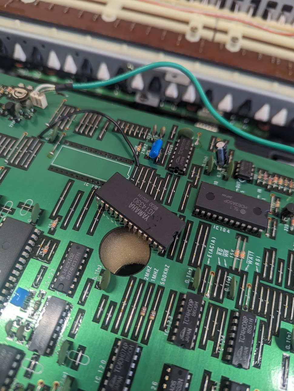
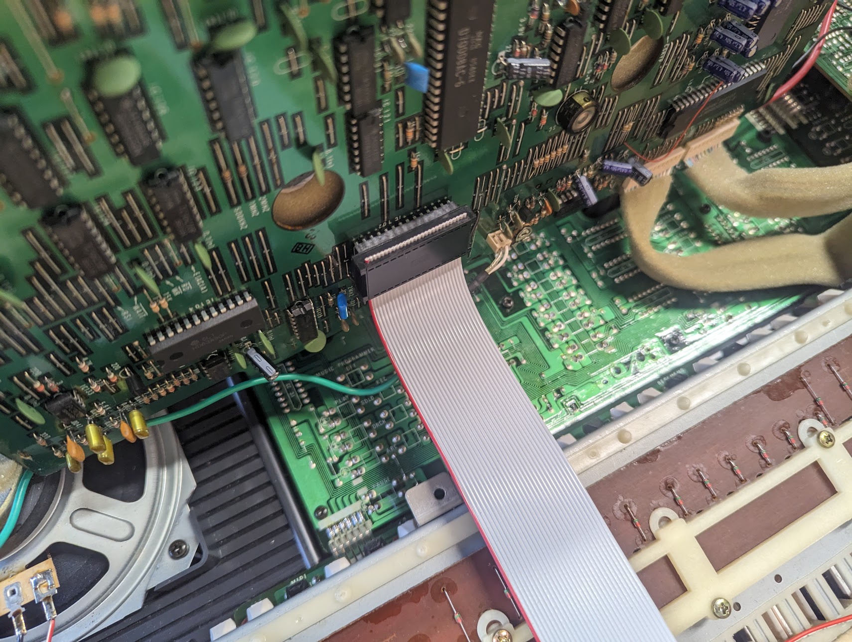
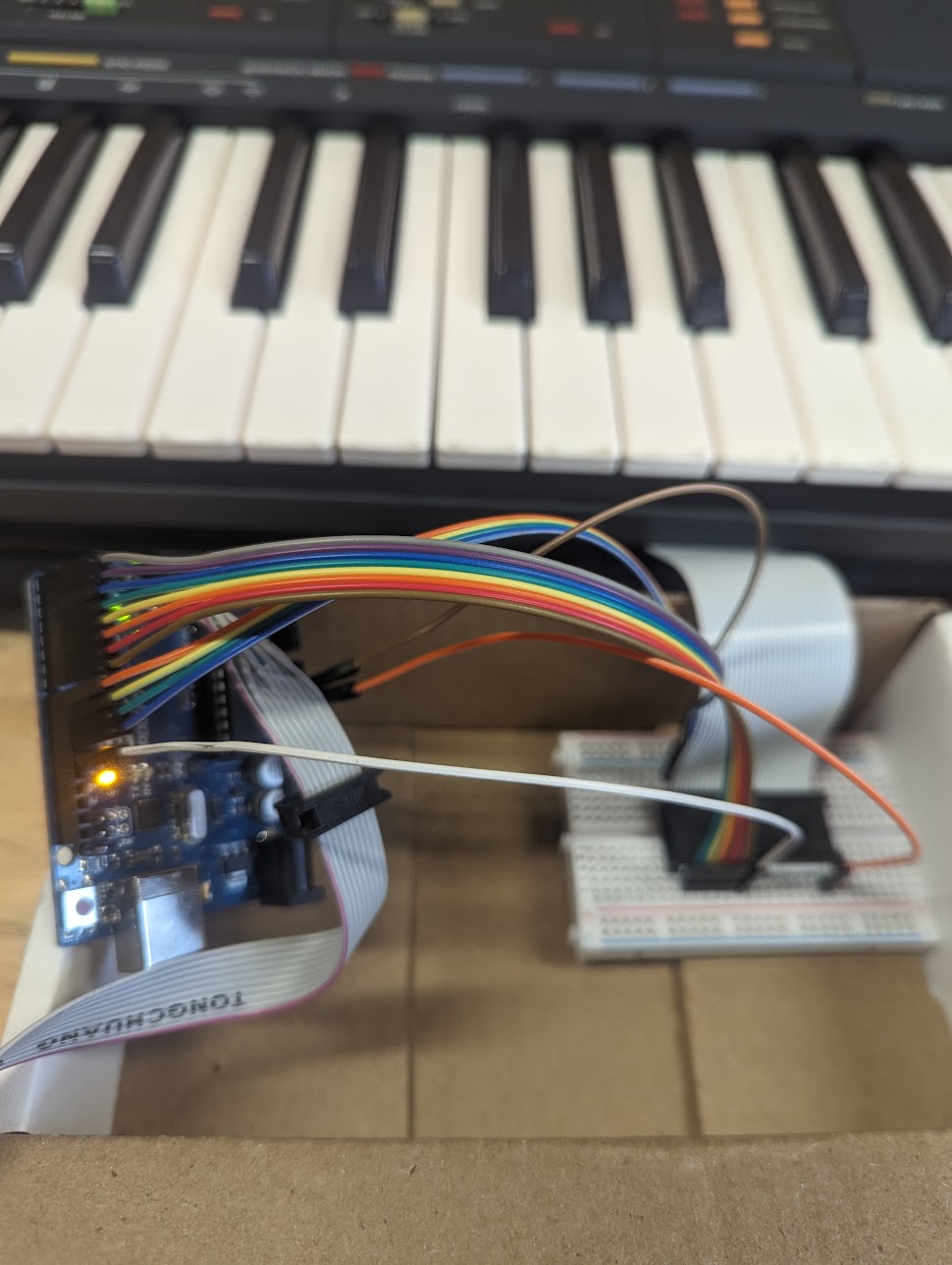
I mean, totally not the right venue for this project, but I'm very excited by it. I mean, this Yamaha PSR-70 was a cheap(ish) piece of trash in its heyday, and a replacement is now less than $200. But it could totally work again, for less than $200 of parts and 60-80 hours of my time! What's not to love!?
1) DTI paralax/sine error. Thanks all for pointing it out. Moved to a plunger that I could align nice and square, and found a 15% or so error.
2) The edge of my cross-slide carriage has a couple of thou of slope. When I changed my setup to a block in front of a block, 3 thou of error difference went away. Next time I get a chance I'll square up that front edge somewhat better to avoid repeating the error caused by the belief that that edge was square vertically.
3) The real kicker: Induction from the power cables. I did a bit more number noodling, and a 60HZ interference with the edges being carried in the read head wiring could *really* mess up the signal, particularly when the frequency of the signal was near the frequency of the current. So yeah, when dialing in close it was becoming grossly inaccurate.
Anyhow, sorry for the long-delayed report. A new (to me) 40 year old non-working synthesizer landed in my lap late last week, and I've been trying to revive it. I've tracked down the not-functioning chip - the panel driver that controls the LEDs and the buttons - and desoldred it and replaced it with a ribbon cable and an Arduino. And tonight I finally got a first set of comprehensible signals to the Arduino. I've now reverse engineered enough of the thing's software (it's got a z80 CPU, so dead easy) to replicate the panel driver's functionality in the Arduino and with luck tomorrow I'll get to generate some sounds!
I mean, totally not the right venue for this project, but I'm very excited by it. I mean, this Yamaha PSR-70 was a cheap(ish) piece of trash in its heyday, and a replacement is now less than $200. But it could totally work again, for less than $200 of parts and 60-80 hours of my time! What's not to love!?
Does your reader generate single ended TTL type signals or RS422 type differential signals?
Differential type signals will be MUCH more immune to external noise.
It might well be that they are differential but the reference is tied to ground so it negates the functionality of a differential signal.......
I assume @PaulL understands that but let us know if not.
The other large factor in noise immunity is the impedance of the sensing circuit. But we can't really change the transmitter or receiver parts of these DROs, but we can provide extra shielding or a better route for the cables, which makes the a lot difference.
It sends the usual A and B edges, and NotA and NotB, each on a wire. But I suspect neither of the DRO heads I have (SINO and TouhDRO) do anything clever with the negated signals.Does your reader generate single ended TTL type signals or RS422 type differential signals?
What I really need to do is find a decent scoping point on the connections, and inspect the noise from the AC, but now that I've routed the cables differently I've lost my incentive to do so.
slow-poke
Ultra Member
If the DRO is only using the single ended TTL signals, that's really not great, chances are if it was using the differential signals your induced noise problems would simply disappear.It sends the usual A and B edges, and NotA and NotB, each on a wire. But I suspect neither of the DRO heads I have (SINO and TouhDRO) do anything clever with the negated signals.
What I really need to do is find a decent scoping point on the connections, and inspect the noise from the AC, but now that I've routed the cables differently I've lost my incentive to do so.
I could send you a PCB that has 3 x DB9's differential in with single ended outputs, that if you placed close to your DRO might solve the problem or at least help. ideally the differential to single ended conversion should be done as close as possible ( like a few mm) from the uC that is interpreting the signals. Either that or get a DRO with differential inputs.
Last edited:
Yeah, I could see that helping. But now that I'm working, I'm loathe to touch it again... Thanks for the offer, however.If the DRO is only using the single ended TTL signals, that's really not great, chances are if it was using the differential signals your induced noise problems would simply disappear.
I could send you a PCB that has 3 x DB9's differential in with single ended outputs, that if you placed close to your DRO might solve the problem or at least help. ideally the differential to single ended conversion should be done as close as possible ( like a few mm) from the uC that is interpreting the signals. Either that or get a DRO with differential inputs.
The other thing I need to check is if the shielding on the cable is correctly grounded. The cables are almost certainly hand-assembled, and it might be easy to "miss" the grounding when putting them together.
The cables are almost certainly hand-assembled, and it might be easy to "miss" the grounding when putting them together.
And if they are differential, make sure the differential reference wire isn't grounded.
The whole point of a differential signal is to run two wires twisted together. Both will see the same noise. By comparing them you know what is a signal and what is noise. It doesn't work if the reference wire is grounded.
Edit - On reading what I wrote, I think it's a wee bit misleading. It does need to be connected to the output signal's reference point (which can sometimes be the output signal ground), and then connected to the input signals differential reference input. Just not connected to the mains ground at either end. Again, the idea is to filter out any noise that is common on both wires, so that only the signal itself remains. It works extremely well in noisy environments.
Last edited: