• Scam Alert. Members are reminded to NOT send money to buy anything. Don't buy things remote and have it shipped - go get it yourself, pay in person, and take your equipment with you. Scammers have burned people on this forum. Urgency, secrecy, excuses, selling for friend, newish members, FUD, are RED FLAGS. A video conference call is not adequate assurance. Face to face interactions are required. Please report suspicions to the forum admins. Stay Safe - anyone can get scammed.

Tool Does Anyone Still Use a Wiggler?

Tool

carrdo

Well-Known Member
Hi All,

I do.

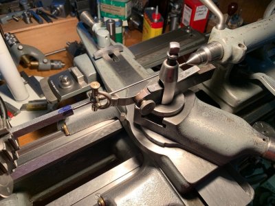
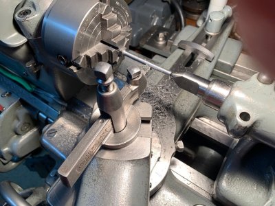
Here is a photo of one which I use to centre a punch mark in the end of long piece of rectangular stock held in the 4 jaw chuck. It takes a bit of setup but with a little practice I can set the punch mark on centre to better than 0.001". It was one of the first tools I ever bought when I purchased the lathe 50 years ago. It was made by Starrett and I don't know if this tool is still made by them. Like everything Starrett, it was not cheap but beautifully made and when needed it is the only way I know of doing something like this. One can increase or decrease the sensitivity of the wiggler by moving the gimble point closer or further away from the punch mark.
 

Attachments

  • 696 A Wiggler Employed to Centre a Punch Mark in the End of a Piece of Rectangular Stock.jpg
    696 A Wiggler Employed to Centre a Punch Mark in the End of a Piece of Rectangular Stock.jpg
    169 KB · Views: 79
I still use one too. For various things.

I have a varient of that principle that I want to use for chambering. That work is done in 10ths. But I have not been able to get it to work as well as a long needle dial test indicator. It isn't repeatable. I have not been able to figure out why not. Some day, I'd like to setup to use it when a group of machinists are here with me to help demystify it.
 
Hi All,

As a follow up to the above.

Turning down the long thin stem on the part held in the 4 jaw. This would seem to be a straightforward operation but to do it right, there is much more to it than meets the eye.

To follow best practice:

The rectangular part in HR steel (from my scrap bin) was first rough formed by milling and left approx.0.025" oversize. There were good reasons to do this to accommodate how the part will be finished and not have problems with other subsequent machining operations . One always has to think ahead when multiple machining operations are involved.

The roughed out part was also left longer than needed for the same reason as above. As well, when the tool bit has to machine right up next to the chuck jaws, clearance issues with some of the older forms of tool holder such as I have dictate this.

When turning long thin shafts like this, tailstock support is mandatory. And if your part can't be left with the recessed centre which subsequently has to be machined away, this extra waste length has to be taken into account also.

When turning thin shafts like this (5/32" finished OD), the use of a half centre is necessary, as shown, so the cutting tool has clearance to be able to start the cut at the minimum diameter.

No seen, but the cutting tool itself has a generous nose radius ground into it on its leading edge. The part drawing itself shows a sharp 90 degree transition between the round stem and the rectangular head of the part. This is not good engineering practice as a sharp transition induces stress risers at the transition point which should be avoided (sometimes it can't) if at all possible. In this case, it was quite possible to have a generous transition radius.

For the best surface finish possible which is needed in this case:

The cut is being undertaken using the finest longitudinal automatic feed rate available on my lathe.
The cutting tool is set exactly square to and a touch below the centre line of the work so the trailing edge of the cutting tool scrapes and polishes as well as cutting through shear. Of course, the tool should be very sharp.
Keep any and all tool/slide overhang to a minimum.
Use cutting oil to improve the surface finish.
When approaching the end of the cut, the transition radius, I release the belt drive on the lathe and then turn the spindle by hand, feeding very slowly into the radius with the leadscrew still engaged. This way the cutting tool does not slam into the transition radius under power and leave chatter/gouge marks.

I do sometimes feed only by hand to have a even finer finish but have had lots of practice doing this over the years.

I am sure I have left things out which others can add. All of this is much longer to describe in words than is done automatically in practice.
 

Attachments

  • 1239 Turning Down a Long Thin Brake Link.jpg
    1239 Turning Down a Long Thin Brake Link.jpg
    171.9 KB · Views: 30
I too use a "wiggler" to centre non-round material in the lathe. For round stock I use a tool post mounted dial indicator. The wiggler also does a great job when turning an eccentric feature on either round or non-round stock.

Here's the one I made years ago from a leftover pushrod end (ordered too many for the airplane I built). I can't claim it as my design but don't recall its origins.

It attaches to the tool holder via a 1/4" stud. The tapered cones thread together. There is a spring behind the sliding stubby point on the left to press its point into a tiny punch mark on the feature's centre.

IMG_0033.jpeg
 
I too use a "wiggler" to centre non-round material in the lathe.

Hmmmm...... Sounds interesting. Please tell us more about this centering non-round material...... I've always just eyed it. A better way sounds intriguing.....

It attaches to the tool holder via a 1/4" stud. The tapered cones thread together. There is a spring behind the sliding stubby point on the left to press its point into a tiny punch mark on the feature's centre.

Could you please provide more info? Is that a bearing or a gimble? How do they thread together when they are on opposite sides. Could you please elaborate?
 
Mine is quite rudimentary. Its a steel rod stick maybe, 0.125" diameter x 12" long. Like piano wire or drill rod. I hold one end in the tailstock chuck & the business end in the (typically 60-deg center drill hole). It just bends slightly conforming to the off-axis runout. I eyeball adjust it first, then with an indicator riding on the rod for more accuracy. One could put the dial on top of rod or anywhere really, depending on what's easiest to correct corresponding runout. The rod has the typical point on the end like typical wigglers. Now maybe a bit OCD but a 60-deg male cone (wiggler) riding in a 60-deg female cone (center drill hole) isn't really 100% accurate because of the off-axis & tangency. That's why you see parabolic center drills for taper turning using TS 60-deg support. So maybe one could bond a bearing ball to the end of the rod so its always in contact with the CD cone?

Don't be tempted to put a DTI ball directly into the center drill hole because the indicator arm can only move in its swivel direction, not perpendicular to swivel direction. If I'm actually planning a setup, its just as easy to drill/ream an accurate hole vs a center drill & use the DTI on the inside surface directly. Or make the hole to accept a pin & indicate off that. But if the part cannot have a hole, maybe the wigglers work on intersecting scribe lines or center pop indentation? I think wigglers are visually intuitive because of the exaggerated lever motion. You can probably get very close to concentric just by adjusting until the extended rod no longer makes a circular extended path.

Yet another way. Put a conical edge finder into the center drill hole. You can visually adjust until the surfaces align visually & then use indicator from there. More compact setup. Ultimately all these methods depend on how good your indicator hole or center pop reference is.
1743789376987.png
 
Please tell us more about this centering non-round material......
Well, it isn't anything too amazing. First off, let me clarify that "non-round" refers to stock or a part being turned in a 4-jaw chuck. It simply comes down to placing a small "centre punch" mark at the centre of rotation.

I've been known to use the mill DRO to find a reference location on the part and then the centre desired. Once over the centre (turn your eyes), I'll put the pointy end of an old, broken edge finder into a 1/2" collet and tap a mark with the mill's quill. Sacrilege I'm sure but it sure leaves a very useful prick punch mark.

For something too long to put in the vise I've used a height gauge on the surface plate to layout the turning centre location and punched the mark the old fashioned way.

Once the part is mounted in the 4 jaw the point on the short end of the "wiggler" is brought into the mark with a little spring pressure to hold it securely. As the chuck is rotated (by hand!) the longer pointer will describe an arc around the lathe centre line. I usually use a tailstock centre as a fixed reference point; it makes any changes very easy to see. The chuck jaws are adjusted until there is no movement on the pointer end. Snug it all up and you're done.

Could you please provide more info? Is that a bearing or a gimble? How do they thread together when they are on opposite sides. Could you please elaborate?
The rod end is a gimble rather like a tie rod end but smaller and with a through hole. I've taken my gizmo apart so you can see all the bits. The end that picks up the register mark is 1/8" rod with a point ground (pr turned) on one end and a collar silver soldered on the other to provide a stop for the spring to press against. The conical end this rod slides through has a 1/4" spigot that goes through the rod end and is threaded 1/4"x40 to thread into the "indicator's" conical piece. The indicator rod is much longer of course, of 3/32" material and is threaded on one end to go into the conical bit. The other end is ground/turned to a point to make seeing any variation easier.

Sorry if this is too detailed and long winded.


IMG_0036.jpegIMG_0035.jpegIMG_0034.jpeg
 
Well, it isn't anything too amazing. First off, let me clarify that "non-round" refers to stock or a part being turned in a 4-jaw chuck. It simply comes down to placing a small "centre punch" mark at the centre of rotation.

I think I might have misunderstood. I thought you were finding center in the 4-jaw with this gizmo. But if I understand now, you already found center using your mill, and you are using this gizmo to center that center. Correct?

Sorry if this is too detailed and long winded.

Impossible for me. I prefer the long version, I just feel bad asking for it.

I really like this! I may have a riding lawn mower ball end like that.

Questions:

Why a 1/4-40 thread? Seems rather exotic. I'm pretty sure I don't have a tap and die that size. Why not 1/4-20 or 1/4-28?

Do you think regular solder would work instead of silver solder? Or what about turning a small head for it that screws on?

Is the spring bore where the collar goes reamed to fit the collar or the collar turned to fit the spring bore? Or neither one?
 
Exactly - the gizmo centers the centre already marked out.
No need to "feel bad" ...

The 1/4-40 thread was used because I have the die/tap (model making) and it provides greater wall thickness for the collar and spring. A 1/4-28 thread would likely be just fine. Just have to watch the spring size. Oh - and the extra fine thread holds tight enough when just hand tightened too.

Regular solder would work fine. There isn't a lot of pressure required to hold the point in the mark. I like the collar idea because it provides a bit of a spigot to centre the spring if soldered on a little bit from the end.

I'm guessing the spring size determined the (free fitting) bore for it and the collar size followed for a loose fit in that bore. In other words, the collar outside diameter is no more than the spring O.D. and the spring shouldn't bind when compressed. Pretty sure the spring just came out of the "someday I'll need that" drawer - certainly didn't wind a spring just for this.

It goes without saying that the bore for the rod pressed against the register mark should be reamed to provide a nice sliding but wobble-free fit. One wants the only side-to-side movement to take place at the rod end gimbal.

Awesome!. I've book marked this till I can find a gimbal.

Thank you!
 
Back
Top