• Spring 2024 meetup in Calgary - date Saturday, April 20/2024. discussion Please RSVP Here to confirm and get your invitation and the location details. RSVP NOW so organizers can plan to get sufficient food etc. One week to go! More info and agenda
  • We are having email/registration problems again. Diagnosis is underway. New users sorry if you are having trouble getting registered. We are exploring different options to get registered. Contact the forum via another member or on facebook if you're stuck. Update -> we think it is fixed. Let us know if not.
  • Spring meet up in Ontario, April 6/2024. NEW LOCATION See Post #31 Discussion AND THE NEW LOCATION

Does anyone have experience reading digital signals to reverse engineer digital control device?

TorontoBuilder

Ultra Member
A certain ventilation company makes a product that provides multiple switching options, from the most basic; off,, low and high fan switch, to the more complex arrangements that make the high fan speed controlled by a humidistat, to multiple fan timer options, to recirculation options that actuate a damper to change the airflow pathway...

The highest level controller has a full blown lcd screen. It is similar to a programmable thermostat but for ventilation. For all their sophistication however they still require a lot of manual user input if you have changing conditions that require varying the recirculation rates and the lack the ability to know when to override a setting when another setting falls outside set parameters, and they dont have an alarm or alert.

37_princ~v~platinum-wall-control.jpg


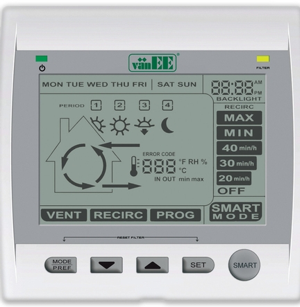
So I want to replace the manufacturers controller with an ESP32 controller that has more settings, options and overrides as well as an alarm function.

I think I can connect an oscilloscope inline with the communications lines going back to the cpu in the ventilation unit to read the digital signals as I change all the settings in order to reverse engineer the code their controller is using.

I think this is viable method to try, any other suggestions? Oh a logic analyzer would likely work too I guess.
 

Susquatch

Ultra Member
Administrator
Moderator
Premium Member
I think this is viable method to try, any other suggestions? Oh a logic analyzer would likely work too I guess.

I have never reverse engineered anything like that. But I can offer a few comments.

What does the business end look like? Is it another controller or is it the regular type controls one sees on a normal system? I ask because the latter is more likely. That would be easier to build a box for.

Most such remote control panels with a box at both ends don't use signals that could easily be decoded by an Analyser. Instead, they use a communications link usually using some standard protocol. Often serial, sometimes other formats. If you can figure out what the protocol is, you can often insert a device to tell you what the signals are. Start by counting wires in the cable and compare that with known standards.

If I were gunna do this, I'd rebuild both ends using a standard protocol. It will take less time and be easier to develop and debug too.
 
Last edited:

PaulL

Technologist at Large
Premium Member
I hate my Hitachi heat pump and it's proprietary protocol and user-hostile controls.
Time to dig for some hobbyist who has hated it even more than me, sooner.
 

slow-poke

Ultra Member
I installed an Electric Power Steering unit from a Chevy Truck into a vintage Mustang ( no more leaky, messy hydraulics, pumps, etc and a fraction of the weight). To accomplish this I had to intercept the messages going back and forth from the main car computer to the CPU in the EPS, and then emulate the messages that normally come from the main computer. It was mildly tricky to figure out and then emulate with a dollar style uC. I have both a digital scope with a bunch of protocol decoders as well as a logic analyzer. Can't recall which one I used possible both. There were lots of CANBUS and OBDII type documents available via Google and I was able to match up what I was seeing with those documents that described what each code represented.

I would suggest picking up a 8 channel clone Saleae logic analyzer ( they are dirt cheap $20 ) and work quite well for simple stuff like this.
 

PaulL

Technologist at Large
Premium Member
I would suggest picking up a 8 channel clone Saleae logic analyzer ( they are dirt cheap $20 ) and work quite well for simple stuff like this.
Yeah, I have the saleae logic analyzer. That thing is pure magic.
My hurdle is getting over doing the work in the hall where the thermostat is installed.
Excuses, excuses.
 

TorontoBuilder

Ultra Member
I have never reverse engineered anything like that. But I can offer a few comments.

What does the business end look like? Is it another controller or is it the regular type controls one sees on a normal system? I ask because the latter is more likely. That would be easier to build a box for.

Most such remote control panels with a box at both ends don't use signals that could easily be decoded by an Analyser. Instead, they use a communications link usually using some standard protocol. Often serial, sometimes other formats. If you can figure out what the protocol is, you can often insert a device to tell you what the signals are. Start by counting wires in the cable and compare that with known standards.

If I were gunna do this, I'd rebuild both ends using a standard protocol. It will take less time and be easier to develop and debug too.

Right now the need is singular, for my friend is a beekeeper. However, there is a potential commercial market.

We can fully change the parameters of our controller, but we can't jailbreak or otherwise mess with the ventilator units firmware. Well we could BUT that would limit the future commercial potential.

I finally got to speak with my buddy Brian and he says easy peasy to hack their firmware data streams and figure out what we need to implement our own schema
 
Top