0.0000328" is 1 micron. Somebody check my math.
Apparently, nobody has offered to check your math....
A while back, an inch got defined as 2.54 cm. That's why the 127 tooth gear works so well.
A micron is a millionth of a meter. In inches, a micron is 0.00003937 - not 0.0000328.
Most references round that to 0.00004 inches, not 0.00003.
When I do conversions, I use 4 significant digits because conversions usually involve multiplication with big numbers and the significant digit difference adds up.
However, when I am just looking at comparative numbers, I just round a micron up to a half ten thousandths of an inch and call it good. A tenths indicator is perfectly capable of showing a half graduation for comparative purposes. In my mind, that's "roughly" equivalent to a micron. I can't discern the difference anyway so I don't give a rats butt about it.
Gelbarts spring is no big deal and definitely not magic. Even the chosen force is purely arbitrary. If you want to make one, just use two plates separated by a pair of bushings and bolted or welded together to look like a tuning fork. He is just using the tensile strength of whatever metal is employed (cold rolled steel in this case) in double cantilever configuration to serve as a spring. Almost any metal can be used to the same way. All he was after was a big measurable (mostly linear) deflection at high forces for calibration purposes.
I tried to watch the video last night but I confess that I fell asleep. From what I recall, most of his numbers are for a 100kg force. This is also easy to calibrate. It's a plain old force/spring - a weight and indicator will work. One could even create a calibration graph if desired. If I were doing it, I'd simply determine the spring constant and be done with it.
Gelbarts suggestions are easy enough, but the book that
@thestelster posted some time ago about testing machine tools is much more comprehensive. Pg 49 has the reference locations and pg 52 covers the specs for tool room lathes. Yes, the book is a hard read, but the difference is that the book also builds an understanding of what is important AND Why as well as listing the specifications.
Thread 'Testing Machine Tools by Georg Schlesinger (7th Edition, 2nd Printing)'
https://canadianhobbymetalworkers.c...rg-schlesinger-7th-edition-2nd-printing.4914/
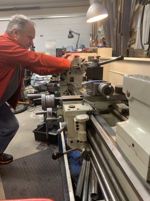
I love the photo of you trying to push over your lathe. Somehow or another my brain translated that into you trying to push a cow sideways in her stall so you could get your milk bucket under her........
I think the biggest problems that any of us will have testing our equipment using Dan's methods is translating that kind of qualification testing into results. I often find myself exploring machine capabilities, but as others frequently remind me, it's the results that matter. And of course the skill of the machinist. It's easy to get fooled into thinking that high precision matters or that higher precision is better than lower.
The danger of course is in evaluating a machine that produces great results, then discovering that the machine is pretty crappy by Dan's standards, and suddenly becoming unhappy with your machine. Yet nothing really changed in the interim.
I also think it's absolutely important to remember that EVERYTHING moves in response to applied forces. It doesn't matter how big it is, or how low the force -
It will move. My only point is that the strength of the materials, the magnitude and direction of the applied forces, and the relevance of the two to what we are trying to do is something that should always be on our minds when we make or measure things.
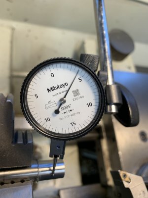
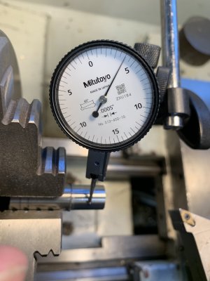
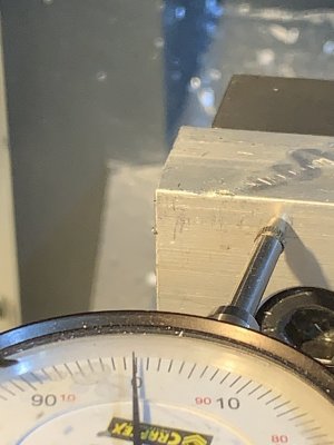
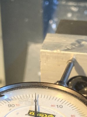
Respectfully I disagree. The stock I was testing against was first turned down. It should be rotating around the actual spindle axis eliminating any alignment differences due to the 3 jaw chuck.
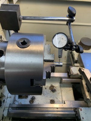
2nd point - I respectfully disagree. The indicator was mounted on the side of the head stock. Pressing on the chuck should indicate the flex of the spindle to the head stock. I think the way Dan tested with the big spring could show the problem with the test you indicate.
If my opinion matters, I mostly agree with you John. My only caveat is actually embedded in my "everything moves" comments above. If you mount the indicator on the head, you are not just measuring the flex of the spindle but also the flex in the headstock itself as well as the indicator holding system. Most of us assume that the latter is neglidgeable, and it usually is, but it isn't zero. On the other hand, I would guess that the headstock movement will likely be a significant part of your measurement, and that where you mount the indicator on the head will also affect it. But I believe that you are fundamentally right. Nonetheless, the post you disagree with may have been trying to make my point above in a more general way. Who knows.
Ya, watch out that Bessy doesn't kick that bucket of yours.......
")
 first error, all you are measuring is if your jaws (scrolling) are centered to spindle, think about it. This can easily corrected for a specific dia (ie test bar) be grinding the jaws at that dia.