A cycloidal drive is a type of high reduction gearing used where compactness, high ratio and zero backlash are needed. These are used extensively in robotics systems such as manipulator arms, indexing devices and precision tables.
I have been working on a design to fit small stepper motors - NEMA 17 and 23, for some time now. The mechanics are deceptively simple, but producing a drive which operates smoothly under all conditions and design loadings is proving to be a real challenge.
3D printed designs are all over the internet. I doubt that any of them will work for more than a few minutes in reality. After many attempts, I have concluded that fused filament techniques and materials have insufficient strength, minimal wear resistance and high deformations. My attempts with Titan-X, ABS/Carbon fibre and nylon all taught some lessons, through various failure mechanisms.
Even though the drives are powered by small stepper motors, the internal torque and contact pressures are extreme and easily deform most plastics. Not all parts need to be hard and solid. The casing is not subject to internal loading and can be designed to use engineering plastics such as Delrin. The cycloidal gear could also be made from Delrin if it is thick enough to resist the in-plane bending forces, but 6061 or even steel would be better. The drive pins however must be rigid and hard, capable of handling the extreme pressures at the contact with the cycloidal disk. And of course the entire system must be rigid and reliable when mounted in service.
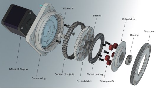
This design is for a NEMA 17 stepper.

Some images of the latest iteration, made from Delrin. The drive pins were made from Teflon to reduce friction. Approximatey 75mmx75mm x 20mm thick.

After an hour of running, the drive pins have been crushed and the system has failed.

Stay tuned....
Don
I have been working on a design to fit small stepper motors - NEMA 17 and 23, for some time now. The mechanics are deceptively simple, but producing a drive which operates smoothly under all conditions and design loadings is proving to be a real challenge.
3D printed designs are all over the internet. I doubt that any of them will work for more than a few minutes in reality. After many attempts, I have concluded that fused filament techniques and materials have insufficient strength, minimal wear resistance and high deformations. My attempts with Titan-X, ABS/Carbon fibre and nylon all taught some lessons, through various failure mechanisms.
Even though the drives are powered by small stepper motors, the internal torque and contact pressures are extreme and easily deform most plastics. Not all parts need to be hard and solid. The casing is not subject to internal loading and can be designed to use engineering plastics such as Delrin. The cycloidal gear could also be made from Delrin if it is thick enough to resist the in-plane bending forces, but 6061 or even steel would be better. The drive pins however must be rigid and hard, capable of handling the extreme pressures at the contact with the cycloidal disk. And of course the entire system must be rigid and reliable when mounted in service.
This design is for a NEMA 17 stepper.
Some images of the latest iteration, made from Delrin. The drive pins were made from Teflon to reduce friction. Approximatey 75mmx75mm x 20mm thick.
After an hour of running, the drive pins have been crushed and the system has failed.
Stay tuned....
Don
Attachments
Last edited: