• Scam Alert. Members are reminded to NOT send money to buy anything. Don't buy things remote and have it shipped - go get it yourself, pay in person, and take your equipment with you. Scammers have burned people on this forum. Urgency, secrecy, excuses, selling for friend, newish members, FUD, are RED FLAGS. A video conference call is not adequate assurance. Face to face interactions are required. Please report suspicions to the forum admins. Stay Safe - anyone can get scammed.
  • The 2026 Calgary Area Meetup is set for Saturday May 30th at 10am. The signup thread is here! Robinhood has graciously offered to host the meetup again this year. Please note that you MUST RSVP to the notice linked above if you wish to come.

CX-600 busy bee mill power on problem

Janger

(The angry Canadian, sorry)
Premium Member
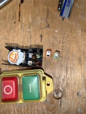
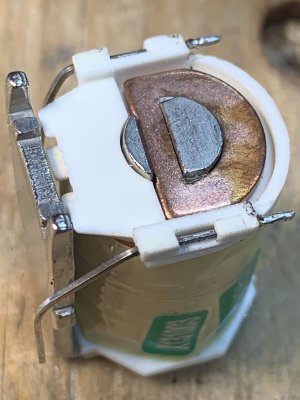
My CX-600 busy bee manual mill won't power on and stay on. The contactor does not sound like it is closing. It will sort of spurt on/off if you push the button hard. I took the switch apart and found dirty contacts. I did some light cleaning and reassembled. No dice. I next checked the relay coil and it measured infinite resistance pole to pole so I guess it's broken wire inside somewhere. This seems just like when motors quit - the coil shorts or breaks and you need a new motor. So why exactly does this happen? I really would like to be able to fix things, fundamentally, instead of replacing parts. 99% of this switch is fine... If I was crazy I could unwind the coil to find breaks and splice it?

BB has these contactor switches on their web site so I'll order on from there or aliexpress. I could just rig up a double pole switch instead...I guess that's a bad idea safety wise.

1786322783859.jpeg 1786330475853.jpeg
 
With unlimited time, I'm sure it would be possible to repair the coil. You would likely need to wind it with new wire...which would probably cost more than a replacement switch! I think any little kink in the wire is a potential new failure point so it is not really DIY-friendly.

For a replacement, the main safety feature is that if the power goes out while you're using the machine, a magnetic switch will not restart it by itself when power is restored. Being a machine tool, that's a good feature.

BTW, is the mill 120V or 240V? If 120V, you only need to switch the hot leg; ie single pole. With 240V, some people still only switch one leg. I think that is crazy and dangerous.

Craig
 
my hypothesis why this happened - the contactor was sputtering some in the months leading up to the failure. Occasionally the mill would not turn on - I think the dirt on the contacts was not helping. The sputtering and machine vibration may have further damaged a weak spot in the coil. Ok that seems reasonable to me...how would one prevent this? higher quality coils? Sputtering prevention? Mercury switches instead of sparking contacts? Solid state parts instead of relays? Five why analysis....


chat gpt derived details on coil failure....

why do coils in motors or relays fail by shorting or breaking?


Coils (the wire windings) in motors and relays fail in two broad ways: **they short** (turn-to-turn or winding-to-winding) or **they open** (a break). Both happen because the coil is an electrical conductor wrapped in **insulation**, and the real stresses on the system often exceed what that conductor/insulation can survive.

### Why coils fail by **shorting**
Shorting usually means insulation between parts of the winding fails, creating a low-resistance path:
- **Overheating → insulation breakdown:** When current is too high (or duty cycle is too long), the coil temperature rises. Heat degrades insulation, eventually letting turns “touch” and short each other.
- **Voltage stress / insulation wear over time:** Higher-than-designed voltage (transients, surges, fast switching) can stress the insulation layer. Microscopic defects can grow until a conductive path forms.
- **Mechanical vibration / movement:** Relays and some motor assemblies vibrate. Motion can abrade insulation, especially at edges, bends, or where conductors are supported.
- **Contamination + moisture:** Dust, humidity, or corrosive residue can reduce insulation resistance and promote leakage paths that evolve into shorts.
- **Electrical transients (especially for relays):** When the coil is switched off, the current wants to keep flowing, producing a high-voltage spike. Without proper suppression, those spikes can punch through insulation or stress adjacent windings.

When turns short, the effective resistance drops, which **increases current**, which causes more heating—so failure can accelerate.

### Why coils fail by **breaking**
Breaking usually means the copper/aluminum conductor (or its connections) fatigues, melts, or fractures:
- **Thermal overload → conductor damage:** If the coil runs too hot for too long, the wire can anneal and weaken; in severe cases it can melt or burn, opening the circuit.
- **Overcurrent events:** A locked rotor, shorted load, or control failure can draw much more current than expected, rapidly overheating the winding.
- **Start/stop cycling and fatigue:** In relays, rapid actuation can flex the wire leads or internal connections. Repeated expansion/contraction can lead to cracks.
- **Thermal cycling + poor strain relief:** If the winding isn’t well supported, temperature changes can move the wire relative to the terminal points, stressing solder joints or crimps until they fail.
- **Arc damage at terminals:** Bad connections create localized heating/arcing, which can burn through the wire or insulation and end up as an open circuit.

### Why you often see both modes in the same system
The coil environment is usually a combo of **heat + electrical stress + mechanical stress**. Often:
- insulation fails first → shorting → higher current → further heating,
or
- overload/short elsewhere heats the coil first → insulation weakens → eventually shorts,
then later
- burning/overheating leads to a full open circuit.

### Key idea
A motor/relay coil is “one component” electrically, but “many failure interfaces” physically: **conductor, insulation, turn-to-turn spacing, terminals, and connection joints**. Failures come from any stress that reduces insulation strength (short) or damages/breaks the conductor/connection (open).

If you tell me the application (relay type, motor size, control voltage, and whether it’s DC or AC), I can point to the most likely failure mechanism and the usual protection fixes (snubbers/TVS/diodes, proper sizing, duty cycle, thermal design, better terminals, etc.).


application is a relay inside a power switch 120V AC 375W contactor where the coil has failed open for a small milling machine.

With a 120 V AC, 375 W contactor/milling-machine setup, a relay coil failing **open** usually means the copper/aluminum winding (or its terminations) overheated or was mechanically/electrically stressed until it cracked or burned open.

Most likely causes (ranked) for **coil open** in this kind of environment:

### 1) Overheating from wrong coil voltage / low coil voltage
If the coil isn’t getting the correct 120 V (or it’s dropping due to wiring, poor connections, or a weak supply), the control behavior can be weird (chatter) and the coil can run hot when it’s not fully pulling in/holding correctly.
- Result: insulation cooks, then the conductor in the winding opens.

### 2) Coil voltage transients / switching spikes
AC control circuits (especially in machines) get spikes from motor drives, other contactors, solenoids, or inductive loads.
- If suppression isn’t appropriate (or was removed/never installed), spikes can damage insulation and overheat the winding.
- Even when final failure is “open,” the damage often started as insulation breakdown or arcing that eventually burns a spot open.

### 3) Loose/bad connection to the coil (most common at terminals, less obvious)
A weak terminal connection can cause localized heating right at the coil leads or terminal lugs.
- Result: the winding lead or internal connection overheats and fractures (open circuit), sometimes before you ever see “whole-coil” overheating.

### 4) Frequent cycling / chatter (mechanical or electrical)
If the contactor repeatedly closes and opens rapidly, or chatters on the coil, the coil doesn’t stay at a steady temperature.
- Result: thermal fatigue plus hot spots → winding open.

### 5) Mechanical vibration/strain in a machine enclosure
Mills have vibration, and contactors can be mounted in ways that stress coil wires/terminals or the internal coil lead joints.
- Result: cracked conductor or cracked solder joint/lead → open.

---

## What to do next (practical troubleshooting)
### A) Confirm coil resistance (and whether it’s truly open)
1. Power completely off.
2. Measure coil resistance across the coil terminals.
- **If it’s “infinite”/open**: yes, coil winding or lead is broken.
- If resistance is much higher than rated: you may have a partially damaged winding.

### B) Measure coil voltage under load (while the coil is commanded ON)
With the machine running normally (or at least with the control command active):
- Measure AC voltage directly at the coil terminals.
- You want it close to **120 V**.
- If it sags (or pulses/chatter), that points strongly to wiring drop, a bad connection, or a control transformer issue.

### C) Inspect and tighten coil terminal connections
- Look for discoloration (browning), looseness, or corrosion.
- Re-seat ring terminals/lugs; tighten to spec if you have it.

### D) Check the contactor/control environment for chatter
Observe whether the contactor:
- pulls in cleanly and stays,
- chatters repeatedly,
- or “tries” to pull but drops out.
If it chatters, the coil is being overheated electrically and thermally.

### E) Verify coil suppression / snubbers (and consider adding the correct one)
For **AC coils inside contactors**, the typical suppression depends on the contactor design and coil type.
- Some contactors already include the correct suppression.
- If yours is missing/damaged (or the switch is a DIY modification), add the *correct* suppression for that control circuit’s switching pattern.

(If you tell me the exact contactor/relay model or whether the coil is AC coil for 120 V, I can suggest what suppression is typically used and where.)

---

## Quick “most likely” diagnosis for your scenario
In a milling machine, the combination that most often leads to **coil open** is:
- **loose/heated coil terminals** and/or
- **supply drop/chatter** causing overheating,
followed by winding/lead fracture.

---

## To narrow it to one cause, answer these
1) Do you know the coil is **exactly 120 V AC** (not a 120 V control transformer feeding it, or a different coil rating)?
2) When it “failed,” did the contactor/relay **try to pull in repeatedly** (chatter) or was it just dead?
3) Can you measure coil resistance? (Even “open” vs “a few ohms” helps.)
4) Is there visible burning/discoloration at the coil terminals?

Reply with those, and I’ll point to the most probable single root cause and the most effective fix.

 
more chatgpt q&a

The coil is 120V AC. The coil is measured completely open by ohm meter. No visible damage to terminals or wiring, no burning or discoloration. There was no chatter but there has been chatter in the past. What is best practice to prevent these problems? Use a different switching technology like solid state solution?


Best practice is to stop the two main killers of relay/contactors: **(1) overheating at the coil/circuit due to abnormal voltage/chatter** and **(2) electrical stress from switching transients and control circuit faults**. A solid-state alternative can help, but it won’t fix a bad control supply connection or poor control switching strategy by itself.

### Best-practice checklist (practical and high-yield)

#### 1) Get control voltage and connections “boringly correct”
- Use the manufacturer-rated control voltage coil (you have 120 V AC, good).
- Verify coil voltage at the coil terminals **while the coil is energized** (not just at the panel). Target is near 120 V.
- Inspect and tighten every control-circuit connection (control switch contacts, wire splices, terminals). You don’t need visible burning for a loose connection to create heat—heat can occur quietly until it fails.

Why this matters: coil open with no terminal damage often still comes from **open inside the winding** due to heating that wasn’t localized at the terminals.

#### 2) Eliminate chatter at the source
Chatter is typically caused by one of:
- low/weak control voltage (or voltage drop),
- mechanical wear/stiction in the relay/contactor mechanics,
- incorrect contactor coil/supply pairing,
- a control circuit that’s “dropping out” due to a wiring fault or intermittent connection.

Best practices:
- Replace worn mechanical contacts/switches that feed the coil.
- Use a contactor/relay with a coil and control circuit rated for the switching frequency you’re actually doing.
- If the control comes from a transformer, ensure it’s sized correctly and not sagging.

Even if it “was not chattering at the moment of failure,” past chatter can cumulatively overheat the winding.

#### 3) Add/correct suppression for the coil/contactor (and any inductive drivers nearby)
For **AC coil circuits**, suppression is often already built into the contactor, but not always—especially with DIY wiring, modifications, or swapped parts.

- Make sure your contactor coil has the recommended suppression (from the OEM).
- If you’re switching a coil with an intermediate relay/SSR/triac driver, the *driver’s* transient behavior can stress the coil supply or nearby circuits; suppression/snubbing across the switched inductive elements or at the driver output may be needed.

Key point: suppression is about reducing electrical stress that accelerates insulation breakdown and internal damage.

#### 4) Control duty and derating: don’t run the coil out of its comfort zone
- Confirm the contactor is used for continuous “hold” properly and not being repeatedly dropped/energized in a way that keeps the coil near its thermal limit.
- If the machine control repeatedly cycles the contactor frequently (startup/brake logic, interlocks, safety chain toggling), ensure the contactor model’s **control duty rating** matches.

#### 5) Keep the coil and enclosure temperature under control
Machines often run hot and dusty. Insulation life drops with temperature.
- Ensure proper mounting, airflow, and that the contactor isn’t in a stagnant hot pocket.
- Avoid placing the control devices next to heat sources.

---

## Should you switch to solid-state?
**For the coil/contactor function inside the power switch:** solid state can reduce mechanical wear, but it depends what you mean by “solid state solution.”

- If you mean using an **SSR to replace the contactor’s mechanical switching of the motor load**, SSRs can work, but they introduce other concerns (heat dissipation, leakage current, surge/EMI, and they aren’t always a drop-in for motor starting/loads).
- If you mean using **solid-state control to energize a coil** (replacing the relay/contact that feeds the 120 V coil), that can reduce chatter mechanically, but you still must:
- provide correct AC behavior,
- handle inrush/EMI correctly,
- and not create new transient/driver issues that can damage the coil.

So: solid-state is not automatically “best practice” unless it’s chosen for the exact load type and has the correct ratings and transient management.

---

## The single most “best practice” move in your scenario
Because your coil measures **completely open** and there’s a history of **chatter**, the highest-impact step is:

1) Measure **coil voltage under energization** (while it’s commanded ON)
2) Inspect and renew the **devices feeding that coil** (control switch contacts, any interlocks, relays/contacts that precede it)
3) Confirm correct coil suppression / correct OEM wiring

Solid state is worth considering later, but only after you’ve confirmed the control circuit voltage stability and removed the chatter mechanism.

---

## Two quick questions (so I can be precise)
1) Is this 120 V coil powered directly from line, or through a **control transformer** / module?
2) What exactly is doing the switching that energizes this coil—another contactor relay contact, a pressure switch, a PLC output, etc.?
 
With unlimited time, I'm sure it would be possible to repair the coil. You would likely need to wind it with new wire...which would probably cost more than a replacement switch! I think any little kink in the wire is a potential new failure point so it is not really DIY-friendly.

For a replacement, the main safety feature is that if the power goes out while you're using the machine, a magnetic switch will not restart it by itself when power is restored. Being a machine tool, that's a good feature.

BTW, is the mill 120V or 240V? If 120V, you only need to switch the hot leg; ie single pole. With 240V, some people still only switch one leg. I think that is crazy and dangerous.

Craig
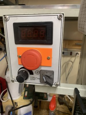
@trlvn Craig it is a 120V mill, just a little guy 3/4HP. But it does have two pole switch - I'll have to look at what the other pole is doing more closely. I think it's a safety circuit which also goes through the chip guard window switch. Like everyone I took that thing off so a single pole switch would probably work.

This contactor has seen intermittent use over a decade. Is this a typical life span for this sort of device?

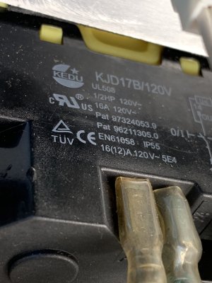
ok I noticed something here - the switch name plate, below, says 1/2HP but the mill is 3/4HP. ... is that a red flag? undersized?

1786374727830.jpeg
 
Looking up the part number, I found a link to a datasheet through DigiKey:


It says these things are rated for rated for 10,000 electrical cycles, which isn't all that many. Old school motor starters (Allen Bradley, Westinghouse, Cutler Hammer, etc, etc) would last far longer and in much more harsh conditions. OTOH, to purchase one of those new would cost a significant fraction of the total for your mill!! IOW, a consumer-priced mill isn't going to include industrial-quality components.

Your contactor seems to be rated for 16 amps which, to me, is more deterministic than 'HP'. Also, the full load should not be going through the coil. The coil only draws enough current to pull the contactor closed. The load current flows through the now-closed contacts. AIUI.

Basically I'd say that your magnetic contactor lasted about the minimum one could reasonably expect. The manufacturer is totally happy since it outlasted the warranty! 😉

Craig
(Not an electrician.)
 
Back
Top