• Spring 2024 meetup in Calgary - date Saturday, April 20/2024. discussion Please RSVP Here to confirm and get your invitation and the location details. RSVP NOW so organizers can plan to get sufficient food etc. It's Tomorrow Saturday! you can still RSVP until I stop checking my phone tomorrow More info and agenda
  • We are having email/registration problems again. Diagnosis is underway. New users sorry if you are having trouble getting registered. We are exploring different options to get registered. Contact the forum via another member or on facebook if you're stuck. Update -> we think it is fixed. Let us know if not.
  • Spring meet up in Ontario, April 6/2024. NEW LOCATION See Post #31 Discussion AND THE NEW LOCATION

Cutting holes to save weight

Chicken lights

Forum Pony Express Driver
254B2F2B-7AE2-41E2-85D0-C672281E2B74.jpeg

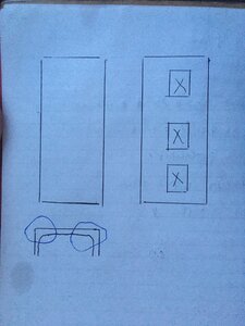
If you took a piece of C channel and cut a bunch of holes in it....how much would you weaken it?
C channel is strongest in the corners, where the most steel is, right?

So as pictured the “x” would be missing. I screwed up the drawing a bit but I was thinking if it was 5-6” tall C channel you could cut a 3”x4” hole every six inches and not really weaken the main piece of C channel
 

RobinHood

Ultra Member
Premium Member
I have not found a value/formula for how much a lightening hole will change the strength of a C-channel.

I do have a big concern with the shape of your proposed cut-outs: each square corner will be the origin of a stress riser and could lead to cracking of your beam.

A better shape would be a round or oval hole. After cutting the material out, carefully dress the edges smooth to eliminate the micro sharp edges left by your cutting tool.

We only ever see round or oval lightening holes in airplane wing ribs to eliminate said stress risers. Those holes serve two main purposes: reduce weight and increase stiffness of the rib (especially since most holes are flared after the material is cut out).
 

Chicken lights

Forum Pony Express Driver
I’m more used to seeing tear drop shaped holes in trailer frame rails, there’s likely an engineering design that supports not having cracks with that shape

I think they’re called dimple dies for race car builders or 4x4 guys punch out the holes and leave them flared for strength
 

Chicken lights

Forum Pony Express Driver
I thought it would be fairly easy to build a jig out of rectangular tubing and use a plasma cutter to cut them out. I guess arguably as easy to use round stock ive no idea on sourcing oval stock.

If it’s steel, and not an airplane, why is stress cracks bad? In this application it’s not a frame or structural, if it cracks weld the crack up

Or am I being too simplistic?
 

CalgaryPT

Ultra Member
Vendor
Premium Member
I’m more used to seeing tear drop shaped holes in trailer frame rails, there’s likely an engineering design that supports not having cracks with that shape

I think they’re called dimple dies for race car builders or 4x4 guys punch out the holes and leave them flared for strength
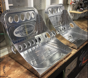
Dimple dies are great and I use them all the time with sheet metal. Similar to a bead roller, the shape profile and stretching of metal adds incredible strength to the bare metal. Just one of the many ways the allies breached the Atlantic Gap by reducing the weight of AL components in aircraft w/o reducing strength. There's a reason they are called "Bomber Seats":

1618194391957.png

These ones are by Jamey Jordan.
 

PeterT

Ultra Member
Premium Member
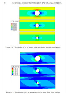
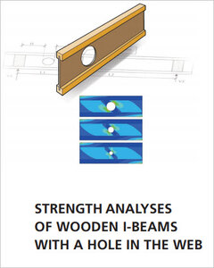
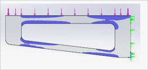
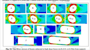
Not really sure by your sketch where the load is being applied. I assume like a beam? Just to give you an visual feel for stress, if you Google 'FEA stress beam with lightening holes' you see some color coded idea of how & where stress levels propagate. Of course this is meaningless without knowing lots more about materials & load distributions & what constitutes failure. And like others are saying a hole is one thing, a hole with a flange is another.

I recall reading about the teardrop holes in trailer frames but it obviously didn't stick in the coconut.
 

Attachments

  • SNAG-4-11-2021 0008.jpg
    SNAG-4-11-2021 0008.jpg
    96.4 KB · Views: 8
  • SNAG-4-11-2021 0009.jpg
    SNAG-4-11-2021 0009.jpg
    43.3 KB · Views: 7
  • SNAG-4-11-2021 0010.jpg
    SNAG-4-11-2021 0010.jpg
    14.3 KB · Views: 6
  • SNAG-4-11-2021 0013.jpg
    SNAG-4-11-2021 0013.jpg
    115.2 KB · Views: 6

CalgaryPT

Ultra Member
Vendor
Premium Member
Materials science is so fascinating. At the old non-destructive NOVA lab on Blackfoot Tr in Calgary they did this stuff in the 1980s. I was a security guard there while I was in school, but they used to show me all this stuff because I was interested. What a great field of study I thought.
 

Chicken lights

Forum Pony Express Driver
Not really sure by your sketch where the load is being applied. I assume like a beam? Just to give you an visual feel for stress, if you Google 'FEA stress beam with lightening holes' you see some color coded idea of how & where stress levels propagate. Of course this is meaningless without knowing lots more about materials & load distributions & what constitutes failure. And like others are saying a hole is one thing, a hole with a flange is another.

I recall reading about the teardrop holes in trailer frames but it obviously didn't stick in the coconut.
I have outside C channel on my trailer that could be lightened up. The holes could be used as fastening. points
 

Dabbler

ersatz engineer
One rule of thumb might be borrowed from I beams, or the triangular beams that you find in a Gradall. IF you remove a round feature off of an I beam and it is less than 1/6 of the overall height profile, you can assume negligible strength loss. If your C section is used in the vertical, the load is unbalanced, so I'd go a little less, say 1/8 of the profile height and a round feature.

There is a rule fo thumb for the distance between features, but I can't remember it. I'd guess 1.5X the feature size in spacing...
 

Chicken lights

Forum Pony Express Driver
16F2D379-1A65-4ED1-A58F-FADFA44B4F49.jpeg It was just something quick to see if the idea is gonna work. I’ll grab a micrometer to measure the C channel thickness tonight or tomorrow
 

Dabbler

ersatz engineer
The size of the hole is related to the height - my bad. so a 6" high I beam has virtually no degradation is strength with 1" holes... with 2" holes the strength is measurably less.

I've seen beams with 1/3 cutouts used in industry, but they were probably over-specified, perhaps 4X the required strength.
 

Chicken lights

Forum Pony Express Driver
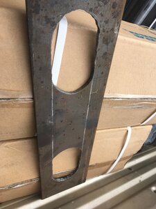
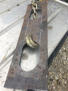
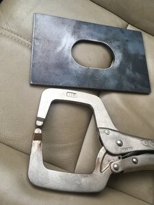
84CD849D-F3F9-4A6D-ABB1-EE92F6C96DFF.jpeg My budget micrometer says the C channel is 1/8” thick. Checked another trailer at work and the stake pockets on it measure the same with the micrometer. Got that plate cut out with a CNC plasma cutter, I’ll start building the jig tomorrow. 2” high hole in 6” C channel leaves 2” of steel on either side of the oval. I think that’ll be fine
 

John Conroy

member
Premium Member
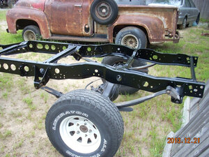
Anybody remember the Ford truck "swiss cheese frame" fiasco of 1980-81? Lots of frames were damaged when subjected to oblique loads.

ford swiss chees frame.jpg
 

John Conroy

member
Premium Member
Imagine driving a pickup down into a steep ditch at an angle then up the other side. Then add the max payload the truck is rated for. The twisting forces are huge and those frames were not up to it. I lived in a farm community where everyone overloaded their pickups. It was not Fords finest hour.
 
Top