CNC Router alignment

SparWeb

Active Member
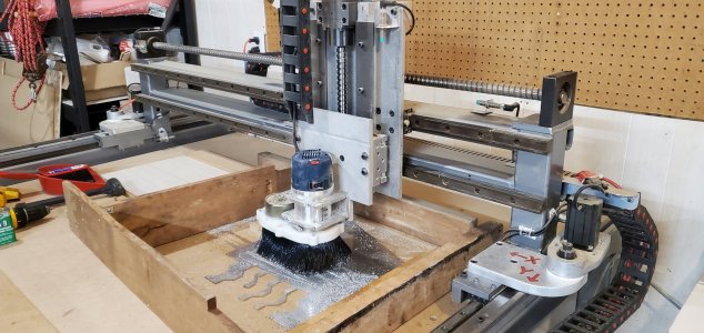
Still getting my CNC router dialed in.
Thanks to many forum members, for your help so far.

With some free time over the holidays, I set about making sure it's well calibrated. Mostly it seems to be OK, but sometimes it isn't. I am still trying to figure out what's going on.
The big picture is this:
- When drilling, it's bang-on, or as close as can be expected with 0.002" or 0.003" backlash on each axis.
- When profile cutting, it's all over the place. Circles are oval by 0.014" in places.

The lumpiness makes the circles "egg-shaped" and rotated by 45 degrees. I thought this was backlash on both axes but it doesn't add up.
I have been cutting circles as profile cuts in aluminum plate. The 1/4" cutter is doing passes only 0.03" deep so it takes 2 passes to cut a circular trench 1/16" deep. The 2 passes coincide exactly. The trench is a bit wider than the 1/4" cutter so it makes separate passes to cut the OD and the ID of the trench. Climb milling all the time, except for the lead-in ramp which is just the way VCarve always does it. I measure the diameter of the trench's OD and ID at various angles around the circle.

The lumpiness of the circles has some definite patterns. I thought I could trace it back to things like backlash, but the backlash isn't that bad (I think). If I try to do the math on the way the backlash could alter the circle, then advancing in one direction could put in +0.003" on that axis, and +0.003" on the other axis. That would make the circle egg-shaped (according to Pythagoras) by only +0.004", not 0.014". I did one of my test cuts by conventional milling direction, and the lobes didn't reverse like I expected. The cumulative error is about the same either way.

To measure the backlash, I used a dial indicator and ran each axis back and forth, measuring the position when the carriage moved to the indicator versus moving away. That's how I got 0.002" on the X and 0.003" on the Y. This isn't enough backlash to account for the oval circles. If you think I'm measuring backlash wrong, I'll post some photos of this set-up so that you can point out any problems.

One more hint: The point where the cutter leads into the plate doesn't seem to be correct. The trough should be a perfect circle, but where the cutter leads in you can see the circle flattens out a little. The path in VCarve looks curved, and the G-code definitely has a lot of X/Y points strung together along the lead in path. This suggests something else is going on. Another hint that I've underestimated the backlash? Flexible cutter?

Side note: The head seems to be nicely trammed in because the bottoms of slots are very smooth and don't have ridges between passes. So I don't think it's that - or is that assessment too hasty?
 

SparWeb

Active Member
It was a DIY project, made from spare parts many years ago. I bought it in September from the guy who built it.
48x32x8 movements. Typical gantry system. The Y-axis has two steppers (one slaved) with toothed belts.
The X and Z axes are driven by single belted stepper motors.
The X and Z carriages are moved by ball-screws while the Y-axes are rack and pinion.
All of the axes are guided by linear guide rails.
The motor driver is a 4-axis Gecko (4-in-one unit). The computer runs Mach 3.

20231125_183808.jpg
 

whydontu

I Tried, It Broke
Premium Member
Are the circles oval no matter the diameter? Just off the top of my head, backlash is a fixed amount and doesn't change with distance moved. Same backlash if you move the carriage 150mm or 600mm. But missed motor steps accumulate, and the ovality of missed steps would be proportional to the circle diameter.

I would also try disconnecting one of the Y steppers, using only one. Maybe the two steppers are getting out of sync?
 
Backlash and direction compound things. When you drill or feed in one direction you basically avoid backlash so an error you see variation in the lead screw along with a bit of play. In the case of a circle the adds in the forces applied by the cutter which further complicates things and increases errors. Slow you feed rate down, second do a finish cut in the opposite direction at an even slower speed with an ultra light step over.
 

SparWeb

Active Member
Something doesn't look right on the X-Axis bearing mount. I'll be examining that carefully soon.
Thanks for the other good ideas - I'll try some other circle sizes to see if the error scales up or not.
Profiling in a circle is turning out to be more useful as a diagnostic than I thought.

To answer the other questions: Yes all of the steppers are the same NEMA style.
I've been using just one feed rate so far - trying a different rate also sounds like it will reveal more information. I haven't set up any finishing passes.
For a little while I will be reluctant to change the cutting program because that would make it hard to compare "before and after".
But I agree that some of the irregularities could be natural results of these roughing passes, and not due to misalignment or problems in the NC machine itself.

I haven't mentioned it yet, but I also realized that this 1/4" cutter is actually cutting like its diameter is 0.255" or more. But when I measure the cutter's blades I get 0.249" So why would a nominal 5/16" slot be 0.325" wide?
I'm not sure if that mystery is related to the suspected backlash. I'm going after the backlash issue first. If I discover what's causing the overcutting in the process, then all the better. Otherwise by fixing backlash I'll be in a better position to figure out why it's cutting over-size. For the record, Mach 3 is using the tool at nominal 0.250" diameter, and has no offsets or tool wear adjustments that I can find.
 

SparWeb

Active Member
Oh, of course, and:
Happy New year folks!
Looking forward to a healthy and creative one myself.
(well, healthiER at least!)
 

Janger

(John)
Administrator
Vendor
Is your code for circles a single G02 G03 command or a lot of G1 little movements?
Hand write a G02 circle(s) and see what happens. Is the code generating the circle if it's little steps not working correctly? Use a gcode viewer to see if it looks off. If the g02 works then it's your code generation. if they both don't work then it sounds like setup.

Maybe instead of cutting a circle mount a pen and see if it can draw a circle with no load.

Use a 90 spot drill and just make a trace line. Then repeat with your end mill. same?
 
Last edited:

SparWeb

Active Member
It's using G1 only for the lead-in ramp, then switching to G3 curves.
I have given it 2.0 in/min to ramp, then switch to 8.0 inch/min while cutting the curved profile.
This is the first cut into the part. The pattern repeats with a smaller circular pass to cut the other edge of the profile.
Here's a snippet from the code (generated by V-Carve Pro):

N180G94
N190X0.0000Y0.0000F8.0
N200G00X-2.3750Y0.0000Z0.2000
N210G1Z0.0000F2.0
N220G1X-2.3710Y-0.1370Z-0.0022
N230G1X-2.3591Y-0.2742Z-0.0045
N240G1X-2.3392Y-0.4107Z-0.0067
N250G1X-2.3114Y-0.5460Z-0.0089
N260G1X-2.2758Y-0.6794Z-0.0112
N270G1X-2.2326Y-0.8101Z-0.0134
N280G1X-2.1821Y-0.9375Z-0.0156
N290G1X-2.2326Y-0.8101Z-0.0178
N300G1X-2.2758Y-0.6794Z-0.0201
N310G1X-2.3114Y-0.5460Z-0.0223
N320G1X-2.3392Y-0.4107Z-0.0246
N330G1X-2.3591Y-0.2742Z-0.0268
N340G1X-2.3710Y-0.1370Z-0.0290
N350G1X-2.3750Y0.0000Z-0.0313
N360G3X0.0000Y-2.3750I2.3750J0.0000F8.0
N370G3X2.3750Y0.0000I0.0000J2.3750
N380G3X0.0000Y2.3750I-2.3750J0.0000
N390G3X-2.3750Y0.0000I0.0000J-2.3750
N400G00Z0.2000

The XYZ steps are only the lead-in. The G3 arcs are quadrants of the same circle, all having 2.375" toolpath radius. The part reference is in the center of the workpiece to make reading the code easier.
With a 1/4" cutter the nominal OD of that profile cut should be 5.000" but it's actually varying from 5.004" to 5.014". The inner profile edge has similar over-cutting and variability.
I have 2 concerns with this: The variability, and the offset. I'm spending more time concerned about the variability right now, and I'll try to solve that first before getting to the offset - unless the solution to one also solves the other.
 

SparWeb

Active Member
I didn't get to spend much time with it today.
I'm concerned about operating it in a cool garage right now (hovering just above freezing). I've been using it nonetheless but normal projects (cutting wood) haven't been very demanding, either. This winter has been ridiculously warm, encouraging me to use it without running the heat in the garage. I'm going to warm things up to a more comfortable temperature, grease all the bearings, and take a close look at the X-axis shaft bearing, because there's a lot of grease already emerging out of the seal. I don't know if it's been like that since I got it, or a symptom of running in a cold shop letting the seal rubber contract and harden. Fortunately, it's not the guide bearings doing this - I do not want to mess with those!
 
I use servos that are setup for Step and Direction, this means their input is like a stepper.

Steppers

Step and Direction input
Maximum torque rating is holding at a solid step, during movement this can be lower, partial or micro steps reduce torque, fast motion saturates stepper causing lose of step.

Servos

Torque rating is typically 100% duty cycle across the entire speed range, peak torque is 4 times at a lower rpm for 10%. Depending on servo can take input like a stepper, in which case counters (position) come into play.


Janger

(John)
Administrator
Vendor
At first glance the code looks good. I think @David_R8 is right get back to the basics. Draw straight lines in both directions and measure what you get versus what you should get. Cold sticky equipment though that seems like a good path to check. Does VCard output gcode with spaces? And maybe with fewer decimal points? like our equipment works down to a tenth! :p
 
Last edited:

SparWeb

Active Member
Speaking of grease...
The grease used in these bearings I would describe as "stringy", not "buttery", so in other words less viscous than the grease I normally have on hand. Ya know.... for my tractor and stuff...
Does EP2 lithium complex make sense?

...and not needing the detergents or anti-corrosion agents would be my guess.


Janger

(John)
Administrator
Vendor
I'm not too sure about greases - I'll leave that to others to comment. Warm up the shop to 20-22C and let the equipment warm up too. And try again? But misalignment, alignment, binding, rubbing, missing steps, especially on a home made machine - that seems to me more likely. If you got a pen going draw a 20" by 20" box and measure the corner to corner diagonals. and the edge lengths.

Nice looking machine I like it. Post some more pictures Steve. I'll go read that other thread again.

What do you think all the parts cost? What control are you using?
 

Janger

(John)
Administrator
Vendor
ok I've re-read your original thread and I see you are using Mach3. I had weird problems like this too with Mach3. It turned out I had the motor acceleration too high and the top speed too high. The setup could not cope with it. Try dropping the motor acceleration to 10% of what you have and cut the max speed lots too - say to 25% or 50%. And try it again. I suspect that is the problem. set your speed to F2 from F8 in your program.
 

SparWeb

Active Member
Thank you for checking!

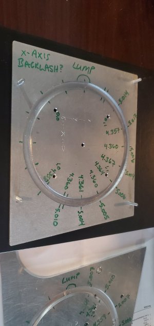
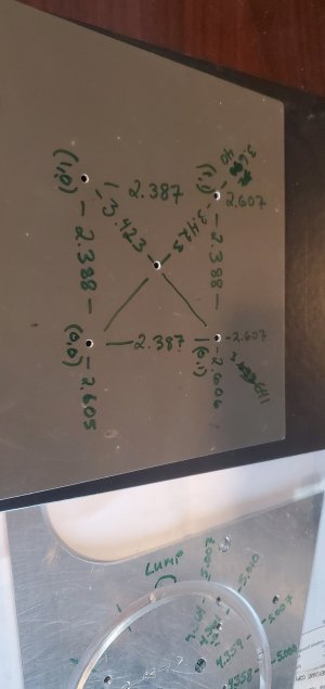
Here's a summary of my measurements.
The trough side has ID and OD measurements written.
Nominal ID should be 4.375" and nominal OD should be 5.000", so way off.

The other side has the X and Y and diagonal measurements across the holes.
These are measured with caliper tips in holes - not inherently accurate but it is repeatable.
Most of these are very close to the nominal measurement.

This is the 3rd piece I've cut (you can see another to the side which has similar results.)

20240101_203612 - Copy.jpg

20240101_203621 - Copy.jpg
 
Top