-
Scam Alert. Members are reminded to NOT send money to buy anything. Don't buy things remote and have it shipped - go get it yourself, pay in person, and take your equipment with you. Scammers have burned people on this forum. Urgency, secrecy, excuses, selling for friend, newish members, FUD, are RED FLAGS. A video conference call is not adequate assurance. Face to face interactions are required. Please report suspicions to the forum admins. Stay Safe - anyone can get scammed.
-
Several Regions have held meetups already, but others are being planned or are evaluating the interest. The Calgary Area Meetup is set for Saturday July 12th at 10am. The signup thread is here! Arbutus has also explored interest in a Fraser Valley meetup but it seems members either missed his thread or had other plans. Let him know if you are interested in a meetup later in the year by posting here! Slowpoke is trying to pull together an Ottawa area meetup later this summer. No date has been selected yet, so let him know if you are interested here! We are not aware of any other meetups being planned this year. If you are interested in doing something in your area, let everyone know and make it happen! Meetups are a great way to make new machining friends and get hands on help in your area. Don’t be shy, sign up and come, or plan your own meetup!
You are using an out of date browser. It may not display this or other websites correctly.
You should upgrade or use an alternative browser.
You should upgrade or use an alternative browser.
CNC 4th Axis
- Thread starter Alexander
- Start date
-
- Tags
- 4th axis cnc rotary indexer stepper
I always thought 4th axis meant about a rotational axis over & above the 3 normal linear axis. But I think there is a more robust definition like below. I found this definition on the internet, so it must be true LOL. I guess you could have a machine with no rotary component but some other 'direction the cutting tool could move' and that might also be a 4th axis? (Although I cant think of one off hand).
The term “5-axis” refers to the number of directions in which the cutting tool can move. On a 5-axis machining center, the cutting tool moves across the X, Y and Z linear axes as well as rotates on the A and B axes to approach the workpiece from any direction.
 I borrowed this image from my machines manual.
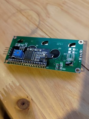
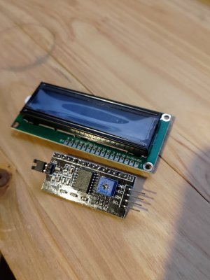
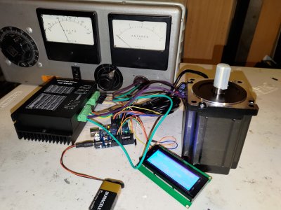
I am starting this project back up. I started following the tutorial @Johnwa linked. Realized my LCD and controller aren't soldered together yet. I'm not very good at soldering but I'll try. If it doesn't turn out good I'll buy the one that is already soldered together 🙄
Attachments
Former Member
Guest
The easiest way to understand axis on cnc is the direction the cutter moves, where it gets complicated is when the work piece moves in conjunction with the cutter and or transfers to secondary holder (lathe mill centers) at this point the the axis count climbs fast.
As an example, x, y, z 3 axis, 1 rotary 4th, 2nd rotary 5th (simple so far) tooling head pivots 6th, tooling rotates around z 7th, transfer to a second cutter head and so on. Seeing some of these machines in action is absolutely amazing.
4 plus a manual 5th can meet most applications that we have.
As an example, x, y, z 3 axis, 1 rotary 4th, 2nd rotary 5th (simple so far) tooling head pivots 6th, tooling rotates around z 7th, transfer to a second cutter head and so on. Seeing some of these machines in action is absolutely amazing.
4 plus a manual 5th can meet most applications that we have.
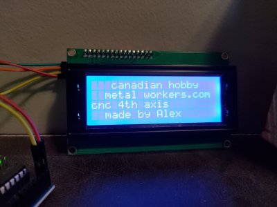
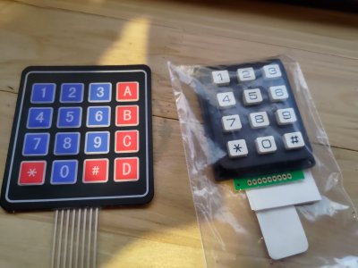
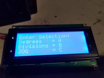
I got my new screen. As soon as I opened it I realized my mistake. The LCD I was trying to use for the tutorial was smaller than it should have been. Once I had the right parts the tutorial @Johnwa shared was easy. Doh! Next step is wiring up a keypad. I have two! Just like before the one I wanted to use is wrong 😀 this time I'll start with the right one. Maybe later I'll try the other one.
Attachments
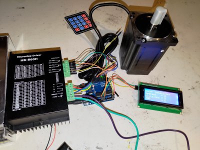
The good news is the program and the number pad work. The bad news is I ordered a DC power supply but this stepper driver is AC Doh! This Microstep Driver also has the inputs labeled differently than the one in Arduino table for dummies guide . I'm hoping it will just work? This might be wishful thinking.
Attachments
gerritv
Gerrit
The manual says AC or DC: http://www.sah.rs/media/sah/techdocs/hb860h_manual.pdf
Although that has the same name. I dont think it is the same part. the manual talks about the closed loop system with encoder. I dont have any of that.The manual says AC or DC: http://www.sah.rs/media/sah/techdocs/hb860h_manual.pdf
I had to Google what you were referring to. I am not exactly sure how I am going to use this just yet. I kind of want to try direct drive, timing belts or worm and worm wheel. Might test it on a big rotary table first. To see how that worksIs there a harmonic drive in between the stepper and chuck?
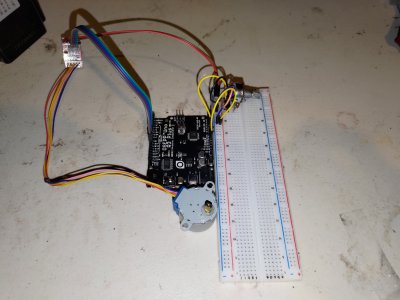
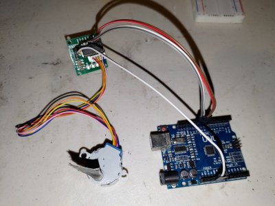
I attached some pictures of my first two stepper projects I completed tonight. One rotates the stepper back and forth one turn and the other rotates the stepper with a 10k potentiometer. I learned a little bit with these tiny parts and I'll try to apply that to the large Microstep Driver over the weekend. I kinda wish the inputs were the same on the big stepper driver but they see to function differently.
Attachments
I had to Google what you were referring to. I am not exactly sure how I am going to use this just yet. I kind of want to try direct drive, timing belts or worm and worm wheel. Might test it on a big rotary table first. To see how that works
I thought it might be given how compact the one in your photo was. They are a great thing and I thought of building a fourth axis based on one, but they are so darn expensive, even from China. imo for dividing you need some sort of gearing, i.e. you need more than micro stepping, else you'll have some large errors between divisions. All depends what you are trying to do of course.
Alright this works! Now I need to figure out how to adjust the steps. The power supply I have for bench testing things will be good enough for now. I didn't try DC power because I believe my driver is actually a cheaper hb860 labeled as the more expensive hybrid version. That is about what I expect from Aliexpress


