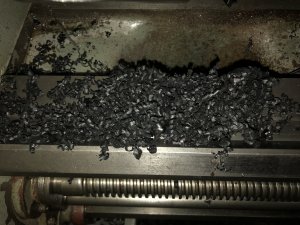
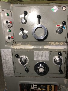
All the levers on the lathe have the same 30mm (nominal) round, black, hard plastic balls on them. My machine was missing 7. They have a M10x1.5 internal thread, a 4mm counter bore and a flat so that the ball can fit up against a shoulder on the lever stem.
I had some black acetal in stock and decided to make my own replacements. Acetal is softer than to OE plastic, but will do for a replacement.
First op was to cut a blank cylinder on the bandsaw. Then over to the lathe for facing, drilling for tap size, counterboring & tapping. Then I mounted the blank on a lever stem (substitute for an arbor) to turn the cylinder to 1mm oversize on the OD and to final length 30mm.
I do not have a ball turner. But I have a milling machine, boring head and a spindexer. I did a calculation of the angle of inclination of the spindexer axis (about 25*) and mounted the blank in a 5C collet. (This is a prototype - hence the hole in the blank from a previous project).

The boring head was set to 15mm radius with a RH boring tool to cut on the inside. This requires the spindle to be run in reverse while the spindexer is spun. This turned out to be a serious concept mistake on my part - as can be seen here.

I was happily turning the crank handle to form the ball when in a split second the sound changed, and next thing I know the spindexer was almost vertical and one of my fingers was bleeding...
So what happened?
Well, the blank had unscrewed on the arbor and in doing so the depth of cut dramatically increased instantly thus the cutter (turning at 1200 rpm) grabbed the part and flipped the spindexer out of the way, jamming my finger to the mill table.
After a few choice words and a bandaid, it was time to regroup and figure out a way to prevent this from happening. The obvious issue is the cutter trying to unscrew the blank (regardless of spindexer rotation) because it is a standard RH tool cutting on the inside and thus needing to be run in REV. I don’t have any LH boring tools. But then I found a LH lathe tool that fit the boring head. Now we can run the spindle FWD, the cutter is cutting on the inside and will have a tendency to tighten the blank on the arbor.
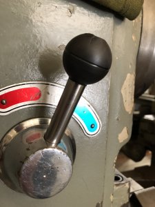
Here is the prototype ball on the Hi/Lo lever.

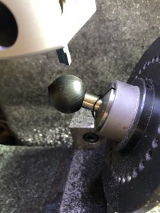
A production ball just finished on the mill. The LH lathe cutting tool is visible. The little point is because I need to leave a flat on the back for the shoulder. It gets filed off when I did the final polishing on the lathe.

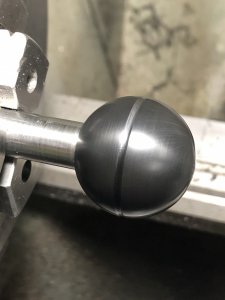
One of the finished balls.

The 8 production balls (7 required + 1 spare) were made uneventfully.
I had some black acetal in stock and decided to make my own replacements. Acetal is softer than to OE plastic, but will do for a replacement.
First op was to cut a blank cylinder on the bandsaw. Then over to the lathe for facing, drilling for tap size, counterboring & tapping. Then I mounted the blank on a lever stem (substitute for an arbor) to turn the cylinder to 1mm oversize on the OD and to final length 30mm.
I do not have a ball turner. But I have a milling machine, boring head and a spindexer. I did a calculation of the angle of inclination of the spindexer axis (about 25*) and mounted the blank in a 5C collet. (This is a prototype - hence the hole in the blank from a previous project).
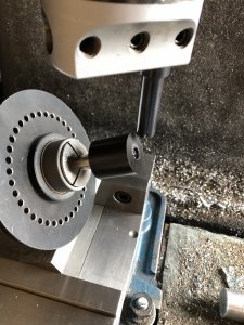
The boring head was set to 15mm radius with a RH boring tool to cut on the inside. This requires the spindle to be run in reverse while the spindexer is spun. This turned out to be a serious concept mistake on my part - as can be seen here.
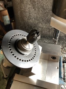
I was happily turning the crank handle to form the ball when in a split second the sound changed, and next thing I know the spindexer was almost vertical and one of my fingers was bleeding...
So what happened?
Well, the blank had unscrewed on the arbor and in doing so the depth of cut dramatically increased instantly thus the cutter (turning at 1200 rpm) grabbed the part and flipped the spindexer out of the way, jamming my finger to the mill table.
After a few choice words and a bandaid, it was time to regroup and figure out a way to prevent this from happening. The obvious issue is the cutter trying to unscrew the blank (regardless of spindexer rotation) because it is a standard RH tool cutting on the inside and thus needing to be run in REV. I don’t have any LH boring tools. But then I found a LH lathe tool that fit the boring head. Now we can run the spindle FWD, the cutter is cutting on the inside and will have a tendency to tighten the blank on the arbor.
Here is the prototype ball on the Hi/Lo lever.
A production ball just finished on the mill. The LH lathe cutting tool is visible. The little point is because I need to leave a flat on the back for the shoulder. It gets filed off when I did the final polishing on the lathe.
One of the finished balls.
The 8 production balls (7 required + 1 spare) were made uneventfully.

