• Scam Alert. Members are reminded to NOT send money to buy anything. Don't buy things remote and have it shipped - go get it yourself, pay in person, and take your equipment with you. Scammers have burned people on this forum. Urgency, secrecy, excuses, selling for friend, newish members, FUD, are RED FLAGS. A video conference call is not adequate assurance. Face to face interactions are required. Please report suspicions to the forum admins. Stay Safe - anyone can get scammed.

Clamp and fixture projects

Janger

(John)
Vendor
Premium Member
You know how it seems you need to make tools so you can make tools for other tools? :D Well I'm working on a clamp project and to mill out the clamp arms I need a big fixture plate. Here are the 6" arms laid out for milling. That's 8" by 15"


1633207570855.webp


This the mill cutting model.

1633207674637.webp


So for that I need a way to hold it down to the table and I'm making a 12x20" aluminium fixture plate with about 50 1/4-20 holes and 50 1/4 dowel pin holes.
 
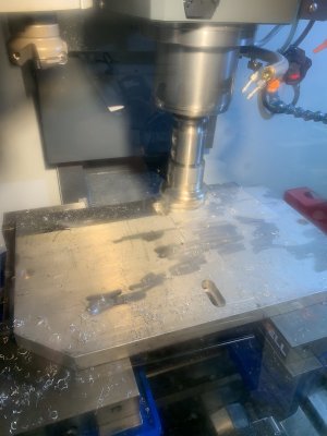
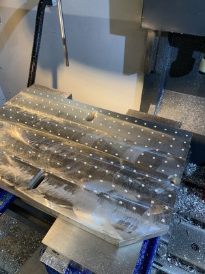
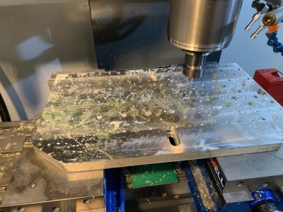
Some progress pics of the fixture plate. Now I need to get out to the shop and do the dowel pin drilling and reaming.

1633208204657.webp
 

Attachments

  • B69ECF69-C298-48C5-B599-ECF34D699423.jpeg
    B69ECF69-C298-48C5-B599-ECF34D699423.jpeg
    309.9 KB · Views: 15
  • D7BFFE08-8381-4CD1-97E1-12C22BB877A8.jpeg
    D7BFFE08-8381-4CD1-97E1-12C22BB877A8.jpeg
    556.9 KB · Views: 16
  • DB697E0A-C732-48A6-B648-953220CA6EC1.jpeg
    DB697E0A-C732-48A6-B648-953220CA6EC1.jpeg
    519.6 KB · Views: 15
12“ x 20” should definitely be big enough for a plate. Is that pic of the arms after nesting? It looks like a lot of waste material left over is there anything else you can machine in those spots or a slight redesign for nesting purpose. Are you casting now or are you saving scraps for the metalcasters?
 
John, I'm not quite getting the utility of the jig plate in this particular application. Is there a spoiler board under the stock or you are OK to re-surface the jig plate after (I assume) the mill has penetrated through the stock into the jig plate?
 
12“ x 20” should definitely be big enough for a plate. Is that pic of the arms after nesting? It looks like a lot of waste material left over is there anything else you can machine in those spots or a slight redesign for nesting purpose. Are you casting now or are you saving scraps for the metalcasters?

There is waste definitely. I don’t see how to do this differently to waste less though. A Redesign of the arms so that they can fit right next to each other might be an idea.

Pete yes I will just face the fixture plate after making the part. No spoiler board.
 
I know whenever I have sent jobs to laser or water cutters they run some kind of nesting software that tightly bundles parts within themselves, even flipping them around. There isn't much swiss cheese left. Can you fake it with a cad assembly & just drag them in visually to reduce waste? Depending on the count you may find a repeating pattern like a nest of 6, then copy/paste to another 6... something like that?

re the hold-down, what I've seen some CNC router guys do is
- plop the metal stock on sacrificial MDF board (plenty flat for cutting 1/8" thick parts)
- run the cnc program drilling 2+ holes per part initially. Maybe the holes are actual feature holes, or maybe dedicated to clamping, your decision
- then they screw the metal down with sheet metal socket screws into these holes using torque driver drill
- then do the complete metal part cutout which are retained by the screws (sometimes tabs no longer required but that varies by application)
- plop on another sheet of metal stock (without disturbing the MDF spoiler), drill through metal, rinse & repeat (because all the thread holes are still in position)
- if the sheet metal type screws bother you or high part count where threaded wood becomes degraded, you could use same principle but insert those steel threaded inserts into MDF

There is no issue skimming your tooling plate after the job is done but seems a shame to loose expensive material every job. You will also likely be cutting across threaded holes with the curved parts. But maybe I just use my jig plate in a different way & this is common practice in cnc? (I'm kind of illiterate in this regard).
 
This is the best nesting I can manage by doing it by hand - there is a lot of waste. Kinda dumb that. Fusion does support nesting parts BUT even though I bought the annual subscription there are still a lot of features which require the 'milling' extension. 5 axis machining for example and nesting - there are other features too. That feature is $2K more per year. blanch. Still as much as that is I've been told Gibbs cam or Mastercam is far more money per year as in tens of thousands more. It's something to know about more advanced machining like 5 axis or more. Go ahead and buy that $500K or $750K 5 or 7 axis machine - you are now on the hook for a new car every year in software to be able to use it effectively. Those little details are not so clear on NYC or Titan's youtube! I don't think computer nesting would help much anyway - I need to add smaller parts which could be included in with the larger ones and then more optimization would be possible.
 
- run the cnc program drilling 2+ holes per part initially. Maybe the holes are actual feature holes, or maybe dedicated to clamping, your decision
- then they screw the metal down with sheet metal socket screws into these holes using torque driver drill
- then do the complete metal part cutout which are retained by the screws (sometimes tabs no longer required but that varies by application)
- plop on another sheet of metal stock (without disturbing the MDF spoiler), drill through metal, rinse & repeat (because all the thread holes are still in position)

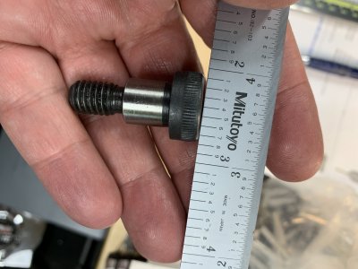
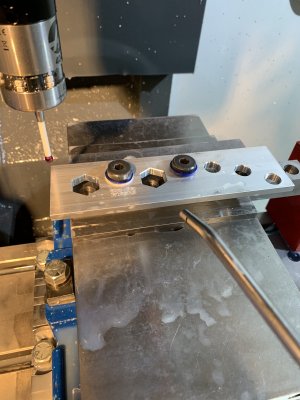
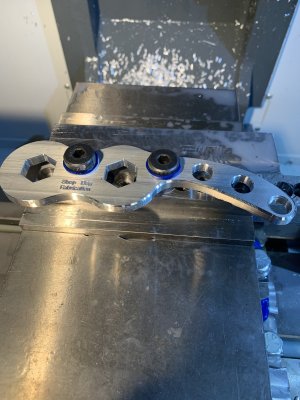
Yup I've done this kind of technique where you do the inside of the part with the stock held in the vise, and then for the next ops hold the part down with screws or some sort here below I'm making vise arms. The second picture shows shoulder bolts with plastic washers underneath holding the part and then proceeding with the outside operations. The shoulder bolts keep the part aligned pretty accurately, better than regular bolts, but maybe not as well as dowel pins going through reamed holes.
 

Attachments

  • 669FC1A7-453A-4018-AFEE-3A95622DDF4C.jpeg
    669FC1A7-453A-4018-AFEE-3A95622DDF4C.jpeg
    329.4 KB · Views: 10
  • 52581C47-14FA-4948-B623-5868B06FE547.jpeg
    52581C47-14FA-4948-B623-5868B06FE547.jpeg
    336.6 KB · Views: 8
  • 79F64083-2C79-4D59-979A-7BBB9E754AE3.jpeg
    79F64083-2C79-4D59-979A-7BBB9E754AE3.jpeg
    409.3 KB · Views: 8
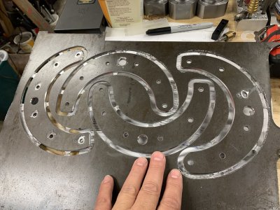
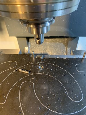
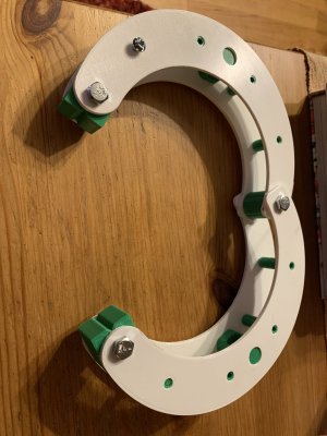
Clamp arms milled. After breaking an End mill Alex checked my program settings. I did it at 60% speed about 6000 rpm and 12ipm instead of 25. Step downs of 0.04” so about 4 passes. Material is 0.144 thick. Flood Coolant. You can see the tabs holding the arms to the plate. Need to band saw the tabs off now and sand the edges.

I printed a mock-up in plastic too.
 

Attachments

  • 10B97BB5-E289-4A35-B3F7-37BAC780F3EA.jpeg
    10B97BB5-E289-4A35-B3F7-37BAC780F3EA.jpeg
    494 KB · Views: 14
  • A65DCFF9-E267-47A9-96D7-199B80C6B697.jpeg
    A65DCFF9-E267-47A9-96D7-199B80C6B697.jpeg
    380.1 KB · Views: 14
  • image.jpg
    image.jpg
    343.1 KB · Views: 13
Dumb question for you @Janger.

Why can't your mill paths overlap to get less waste? It seems like you are deliberately avoiding cutting where you have already cut. Just eyeballing it, it looks like you could save 20% or so by overlapping the paths.
 
Wow cool stuff way beyond me. Are you planning on selling any finished product in the end after all that work of figuring out how to do it?
 
Dumb question for you @Janger.

Why can't your mill paths overlap to get less waste? It seems like you are deliberately avoiding cutting where you have already cut. Just eyeballing it, it looks like you could save 20% or so by overlapping the paths.
No dumb questions. I'll try to answer.

1635553549432.png


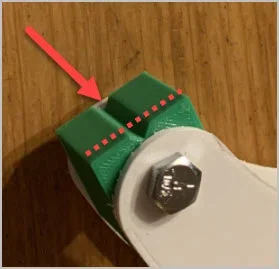
Here you can see where the tab attaches to the stock. I kept the pieces well apart so the tabs always attach to the stock AND I don't make any islands of unattached material. The EM is pulling up like crazy on the material so anything that is not well supported could come off and do all kinds of damage. This is also the first time I've done milling with tabs so I wanted to be pretty conservative. No problems (well after I busted a EM there were no serious future problems). The design of the clamp arms means there is a lot of waste. A better more nestable design for the arms would help. Maybe V2.

There are some guys making these clamps on kickstarter or something if you want to buy some. I don't know if I'll try to sell any - first let me finish some!

Also nesting on a waterjet or plasma table is simpler as you don't have to worry so much about parts going flying. You could bump them really close together then.

I was thinking aluminium plate might be another way to go to make the arms - these clamps are going to be heavy.
 
Last edited:
Not sure if you finalized the jaws but I'd extend the block dimensions so the sides don't interfere with part fully engaging the Vee, if I'm interpreting the mockup correctly.
 

Attachments

  • EDT-2021-10-29 6.36.51 PM.webp
    EDT-2021-10-29 6.36.51 PM.webp
    8.5 KB · Views: 1
Ok now I have a question. I need to make this soft jaw to hold some 0.375 rod to make the clamp standoffs. what size should the holes ideally be? 0.376? 0.377? 0.385? I've done this before making the holes the exact size as the stock. That worked but I had to knock the parts out with a hammer after loosening the jaws. Thoughts?


1635561037855.webp
 
No dumb questions. I'll try to answer.

View attachment 17957

Here you can see where the tab attaches to the stock. I kept the pieces well apart so the tabs always attach to the stock AND I don't make any islands of unattached material. The EM is pulling up like crazy on the material so anything that is not well supported could come off and do all kinds of damage. This is also the first time I've done milling with tabs so I wanted to be pretty conservative. No problems (well after I busted a EM there were no serious future problems). The design of the clamp arms means there is a lot of waste. A better more nestable design for the arms would help. Maybe V2.

There are some guys making these clamps on kickstarter or something if you want to buy some. I don't know if I'll try to sell any - first let me finish some!

Also nesting on a waterjet or plasma table is simpler as you don't have to worry so much about parts going flying. You could bump them really close together then.

I was thinking aluminium plate might be another way to go to make the arms - these clamps are going to be heavy.

You could always mill the holes in your clamps first and use them to hold the clamps down to your wasteboard. that would allow you to remove the tabs. you just have to make sure the screws are tight or the clamp body's could shift during cut operations
 
You could always mill the holes in your clamps first and use them to hold the clamps down to your wasteboard. that would allow you to remove the tabs. you just have to make sure the screws are tight or the clamp body's could shift during cut operations

EXACTLY what I was going to suggest. Glad I read further down before diving in. In addition to that, I'd suggest that more holes wouldn't hurt the function but might improve hold down.

@Janger - as far as I'm concerned, weight is no issue. Heavy Clamps are not necessarily better but they do "feel" better!
 
Ok now I have a question. I need to make this soft jaw to hold some 0.375 rod to make the clamp standoffs. what size should the holes ideally be? 0.376? 0.377? 0.385? I've done this before making the holes the exact size as the stock. That worked but I had to knock the parts out with a hammer after loosening the jaws. Thoughts?

I can point you to some tolerance fit sources, but the very first question will be what is the size & variation of the rod diameters? If its like O1 drill rod, might be 0.375 +/- 0.0005". And my experience with that stock is the section can be slightly eliptical which isn't quite the same circular section with +/- tolerance. If you are using more conventional stock, all bets off. Ground shafting is better but i suspect you might not be milling that?

I haven't done enough jig work like this to know for sure, but I suspect why they work (or don't) is aluminum is more ductile & distorts a bit during clamping. Say the 2 left shafts are plus 0.001" & the right one is minus 0.001". Now the jaws are bridged open on the big ones, no way the right part can be gripped as tight. To the extent it may not be tight at all or worse, come loose during machining. If gronk solves the problem (jaw distortion) that may be acceptable for the batch run, but just this issue could be a possibility. I've set up so called identical parts in my mill vise for same operation face milling & had a few surprises. What usually solved the issue was paper or something to take up the varying gap. Your self centering application would probably not lend itself to this unless the jig was a series of Vees.
 
here's my take on this: Make the holes .375 BUT there's a trick to it (there's always a trick)

holes.webp


You mill the holes with a .005 to .010 spacer, then after the boring is complete, relieve the holes (shown in red) an additional .020 - this relief amounts to about 15% of the diameter (if you include both sides) when complete. Now there is no way for the jaws to 'pinch' the pin when released, and when you tighten you get positive, repeatable clamping.
 
X2 was Dabbler said. Works very well, especially with aluminum soft jaws.

If you want to go really fancy, you can make your jig holes with just 3 points of contact. Steve Barton over at Solid Rock Machine Shop shows that in one of the videos (sorry, can’t find which one at the moment).
 
Back
Top