-
Scam Alert. Members are reminded to NOT send money to buy anything. Don't buy things remote and have it shipped - go get it yourself, pay in person, and take your equipment with you. Scammers have burned people on this forum. Urgency, secrecy, excuses, selling for friend, newish members, FUD, are RED FLAGS. A video conference call is not adequate assurance. Face to face interactions are required. Please report suspicions to the forum admins. Stay Safe - anyone can get scammed.
-
Several Regions have held meetups already, but others are being planned or are evaluating the interest. The Calgary Area Meetup is set for Saturday July 12th at 10am. The signup thread is here! Arbutus has also explored interest in a Fraser Valley meetup but it seems members either missed his thread or had other plans. Let him know if you are interested in a meetup later in the year by posting here! Slowpoke is trying to pull together an Ottawa area meetup later this summer. No date has been selected yet, so let him know if you are interested here! We are not aware of any other meetups being planned this year. If you are interested in doing something in your area, let everyone know and make it happen! Meetups are a great way to make new machining friends and get hands on help in your area. Don’t be shy, sign up and come, or plan your own meetup!
You are using an out of date browser. It may not display this or other websites correctly.
You should upgrade or use an alternative browser.
You should upgrade or use an alternative browser.
Changes to Fusion 360 for personal use
- Thread starter PeterT
- Start date
G1 X102.877 Y157.638 F10800.000
I don't see any G0 rapid moves in a randomly chosen gcode model for 3d printing. Lots of lines though have a F10800.000 feed rate like the above example. That's 425 inches/minute which is rapid on my mill. That gcode was generated with the Prusa slicer software - I think it's a variant of something open source.
I don't see any G0 rapid moves in a randomly chosen gcode model for 3d printing. Lots of lines though have a F10800.000 feed rate like the above example. That's 425 inches/minute which is rapid on my mill. That gcode was generated with the Prusa slicer software - I think it's a variant of something open source.
I use AlibreCAD and have for more than 10 years even as it was Geomagic for a while. For the CAM I was using AlibreCAM (MecSoft CAM) but that's been discontinued now and I've had to buy a MecSoft 4 axis license. All in all I'm still paying less than Fusion 360 and although I recently looked at it I really have never been able to get y head around it. Don't like MecsoftCAD either.
There is an Alibre light version that was written up in Model Engineer's Workshop but the CAM part is pretty simple IIRC.
There is an Alibre light version that was written up in Model Engineer's Workshop but the CAM part is pretty simple IIRC.
gerritv
Gerrit
They make this a challenge to find, but still there: https://www.autodesk.com/products/fusion-360/personal
You need to renew this every year by re-downloading, near the end of the year it starts letting you know in the title bar about # of days left.
Gerrit
You need to renew this every year by re-downloading, near the end of the year it starts letting you know in the title bar about # of days left.
Gerrit
This is bad news. They are taking away key features for hobbyists such as the ability to export to various file types.
Tried using Fusion couldn't get my head around the program concept although I respect those who can. Aren't I glad I didn't. Just saying
Where have you been hiding @David_R8
At the moment, as long as AlibreCAM still works with the native AlibreCAD AD_PRT documents I'm staying with Alibre. But their Rev 23 has an issue with exporting STEP files. A drawing exported as STEP and then re-imported has flaws. VisualCAM also creates flaws in the imported step file. Both Fusion360 and SprutCAM appear not to have problems with the imported step file.
None of this would be an issue for me if Alibre hadn't decided to stop working with MecSoft. They claim MecSoft doesn't want to upgrade their plug in. I've heard rumors that the native file format from Alibre has errors and MecSoft won't work with them because Alibre won't fix the problems. Given that Alibre can't import it's own exported STEP file I'm guessing the issue is with Alibre. A good reason not to choose them I guess.
None of this would be an issue for me if Alibre hadn't decided to stop working with MecSoft. They claim MecSoft doesn't want to upgrade their plug in. I've heard rumors that the native file format from Alibre has errors and MecSoft won't work with them because Alibre won't fix the problems. Given that Alibre can't import it's own exported STEP file I'm guessing the issue is with Alibre. A good reason not to choose them I guess.
Attachments
They make this a challenge to find, but still there: https://www.autodesk.com/products/fusion-360/personal
You need to renew this every year by re-downloading, near the end of the year it starts letting you know in the title bar about # of days left.
Gerrit
I just did this. I can still open my previous work and no longer have the expired notification. Thanks for posting the link!
deleted_user
Super User
Forgive me if posting this same info twice violates the rules. I posted this in a 3d printing thread but it is more apropos here:
A word about Fusion 360, renewals, and the limit of 10 editable files.
Firstly, Autodesk pondered eliminating the free hobbyist license and found that they'd lose their entire hobbyist market to other vendors all too happy to take over the gateway to commercial licensing.... autodesk quickly backed down and wont ever revisit this. Think of it as their "new coke" experiment.
Renewals can be a pain as my last one was, but it is worth it for free.
The new software as a service model sucks. I hate it and I will not support it. I've been buying commercial cad programs from autodesk for 3 decades and have spent thousands and thousands on upgrades. once they moved to software as a service they lost me. I started on CAD when the programs were still DOS based.
I maintain an XP desktop and a windows 7 (IIRC) desktop to use exclusively with my last paid versions of autocad.
One way to defeat the 10 file limit when designing new small parts for different things is to create a new project, entitled "The Universe" for instance, and then create a new file entitled "The Shop". Then just add components like "Lathe" and Mill" and sub components "spindle mount"
I have files for wood shop, metal shop, garage, household, ebike. I have hundreds of parts in these files. Screw their 10 file limit.
Addendum:
When you work in one of your ten permissible fusion files, it helps to think of components as files. Dont add new actual files, add new components. They don't ever have to relate to the other components in your file.
If you have a decent modern computer you can have many many components without bogging down.
deleted_user
Super User
That is a lot of effort expended, when the 10 file limit is actually not much of a problem for hobby use. Still the best deal around.
It is not really any effort, in fact it is far less than swapping files back and forth which I did at first. Prior to these changes I used to model components in individual files, then assemble them later into a machine. That went out the window.
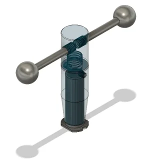
Case in point, here is the roller height Vernier gauge I designed for couple small etching presses I designed as gifts for artist friends who liked travel the arts festival circuit in the US. Six parts I kept toying with the get the right scale and feel right since it is one of the most touched components on the presses.
Regardless, when you use the program frequently enough and develop habits any method becomes ingrained and not much bother... I made my suggestion for those who dont use it often enough to learn to fast swap editing abilities.
Attachments
gerritv
Gerrit
I learned early on in Fusion and Inventor to create new components in an assembly, not as separate files. Lots of using the 'project' feature to build the interface to the next part. So I suppose in essence I was using your method in the first place 🙂 each file is an assembly. Except Drawings, those are separate but generally don't need editing after initial creation.
The GUI does a pretty decent job of letting you move files from ReadOnly<>Editable, one click and you see which 10 are editable, usually not all need to be. I find it only happens when I am bouncing between projects a lot.
There is always the option of $80 for a month of full access to get past some big thing.
I keep loose tabs on the new Solidworks for makers which is their recent 99$/yr pricing model. Hard to find thorough feedback, maybe its still too new. Rumor is that the EAA membership & veterans heavy discount will be no more & this price model will replace. Not sure about education versions I've heard they are pretty sticky accredited institutions/program verification. They define commercial as >2000$. The drawings are watermarked. Possibly the parts are digitally 'marked' (my personal hunch). If you aren't selling stuff or bidding out jobs to CNC folks then who cares.
Rather a painful video to get through, but according to his rambling, doesn't look to be any maximum file saves. He says bit of rigmarole to first load files to the SW cloud, then back to local machine, but ultimately you can save your own files for real. So possibly they took some of the Fusion360 pain points & made them more appealing. There is no CAM component to SW like F360. Depending on your parts/assembly complexity your PC has to be up to snuff. The current version is Win-10 only, Win-7 & prior is bye-bye. But I'm not clear on 'web version' if that means you are running on the web (so PC/OS agnostic). Or is it just handshaking to say you have a SR# & now run it locally. That would be my guess.
Rather a painful video to get through, but according to his rambling, doesn't look to be any maximum file saves. He says bit of rigmarole to first load files to the SW cloud, then back to local machine, but ultimately you can save your own files for real. So possibly they took some of the Fusion360 pain points & made them more appealing. There is no CAM component to SW like F360. Depending on your parts/assembly complexity your PC has to be up to snuff. The current version is Win-10 only, Win-7 & prior is bye-bye. But I'm not clear on 'web version' if that means you are running on the web (so PC/OS agnostic). Or is it just handshaking to say you have a SR# & now run it locally. That would be my guess.
gerritv
Gerrit
Supremely painful and IMHO not a correct overview (I watched another painful 10 minutes of his comparison video. There is a reason why he has so few subscribers??
Fusion360 Personal also has no limit on # of files, just that you can only have 10 editable. But otherwise no limit. If you are designing things in 'the 3D way' meaning 1 file is an assembly that contains components, then as TorontoBuilder and I have found there is no actual limit. As an example I have a 3D model of my lathe, every single casting, bolt, nut and washer. It is one file. I either have it editable or not depending on what I am doing.
Fusion360 Personal has a $1000 limit on profit so not a huge diff to 3DX SW. Except Fusion360 is $0/yr.
Fusion360 has CAM, including some 4th axis rotary axis capabilities. No rapdis, no tool changes but again not a big deal if you are running a converted boat anchor. Or in my case a gantry mill that mimics a Tormach 1100m. On typical parts I run 15 minutes, no a lot of time to be saved with rapids. I used the SW CAM for a year via EAA, painful. I didn't renew my EAA as a result. 3DX SW has no CAM apparently.
3DX SW and Fusion360 boh download program stuff to your PC. In the case of SW it is Java based, a pain IMO. Both store your files first in the cloud, both support getting your files local to your PC. The 3D Guy specifically is wrong on not running the program locally "Powerful parametric modeling you know and love with SOLIDWORKS CAD—installs locally", so just like Fusion360
Learning support, there is a vast amount of F360 help on YT, not so much for SW and less for 3DX SW. Not sure how much of SW lerning is useful on 3DX SW.
Fusion360 has the option of monthly (CA$80) is you need access to the full package. Whatever you do sticks, so e.g. some of the CAM goodies still leave you with the toolpaths on those files.
3DX SW watermarks your files, a non-starter for me. "You cannot open up files created with your Maker account within a commercial or academic platform. This digital watermark is added to native 3D file formats, such as .3dxml, .sldprt, .sldasm, and .slddrw." As a result you have no path from 3DX SW to SW, unlike Fusion360 where the same files can be used with or without a licence fee. And so you also can't share/collaborate with someone who has the full package.
Thank you PeterT for helping me confirm my choice of CAD/CAM sw 🙂
Gerrit
@gerritv I think I learned more from your post than my internet wanderings thus far. I mentioned my hunch there may be some 'digital watermarks' being applied behind the scenes to the parts files themselves. Not just 'hardcopy watermarks' as in applied to drawing files for paper format. The collaboration/cloud/sharing thing is likely a happy sounding diversion. This might explain the upload step first before you can download to local drive. Now that your file has that special little embedded tracking device installed, they no longer care where you store it. Maybe I've misinterpreted but nothing surprises me.
Regarding your 'parts within an assembly' like your lathe example. I see what you are saying as a potential workaround to the F360 specific issue. But (again coming from SW environment) this can have some downsides too. Opening the file means the program has to swallow that whole whale in order to commence working on an individual part. If the part count is high, parts are complex, mate references are many, maybe sub-configurations or design tables, colored components... all that stuff has to be in memory essentially. That's a lot of overhead to just work on a part. Even just moving around the model, rotating, zooming etc. it needs to grind the whole assembly. If your ram/processor/VC are up to snuff then who cares. But it would be nicer to just work on the part & then deal with the assembly as a secondary operation, which I think is the workflow norm. I know SW has many specific commands for large part count assemblies to 'simplify' sub-assemblies within major assemblies, to improve rebuild/processing time & mitigate crashes. Maybe most hobbyists would not encounter this but I wouldn't rule it out. A model locomotive parts count would be getting up there. I haven't done a full assembly of my radial in a while but I cant detect any lag. Mind you on that I typically use rotate/copy tricks to a seed cylinder sub-assembly which is trivial processing vs 5 times discreet (different) part components. My PC is good but not like a workstation good or anything. In some other post we were talking about PC benchmarking, where you download a standard model & it performs some rebuild task. If you get 2 seconds you're a YouTube hero. If you get 60 seconds its PC upgrade time. I thought I saw this for F360 but lost track.
Re learning resources, through our library they have 'free' membership to LinkedIn Learning (formerly Lynda). It is a treasure trove of video learning for all kinds of apps. I think normal cost is like 400 smacks/year or so. Maybe your library has similar? i just sign in through the library card portal after giving my card ID.

 www.linkedin.com
I actually came close to exploring F360 last year when all the shenanigan's commenced, so now I'm in a holding pattern until the dust settles. Maybe it has now & the result is give them a grand & all your problems go away, I dunno. I don't have CNC or 3DP requirements at the momemnt, but that could change with some time on my hands. OnShape is long those pricing lines for 1-time purchase but it has pros & cons from what I've read.
 www.onshape.com
I think digital subscriptions are here to stay, but some of the manipulation tactics bug me. Microsoft Office 365 is $100/year for multi-device installs. I would think there is a lot more combined programming & maintenance effort in the suite of their 5 or 6 apps. But its a numbers game. CAD is a small market vs word processing & spreadsheets is a big market. I'm not tech savvy enough to hang onto a Win-XP box to run an old version of whatever. But I know people who do exactly that. The same guys at garage sales buying up the year dusty 2002 motherboards & graphics cards LOL.
Regarding your 'parts within an assembly' like your lathe example. I see what you are saying as a potential workaround to the F360 specific issue. But (again coming from SW environment) this can have some downsides too. Opening the file means the program has to swallow that whole whale in order to commence working on an individual part. If the part count is high, parts are complex, mate references are many, maybe sub-configurations or design tables, colored components... all that stuff has to be in memory essentially. That's a lot of overhead to just work on a part. Even just moving around the model, rotating, zooming etc. it needs to grind the whole assembly. If your ram/processor/VC are up to snuff then who cares. But it would be nicer to just work on the part & then deal with the assembly as a secondary operation, which I think is the workflow norm. I know SW has many specific commands for large part count assemblies to 'simplify' sub-assemblies within major assemblies, to improve rebuild/processing time & mitigate crashes. Maybe most hobbyists would not encounter this but I wouldn't rule it out. A model locomotive parts count would be getting up there. I haven't done a full assembly of my radial in a while but I cant detect any lag. Mind you on that I typically use rotate/copy tricks to a seed cylinder sub-assembly which is trivial processing vs 5 times discreet (different) part components. My PC is good but not like a workstation good or anything. In some other post we were talking about PC benchmarking, where you download a standard model & it performs some rebuild task. If you get 2 seconds you're a YouTube hero. If you get 60 seconds its PC upgrade time. I thought I saw this for F360 but lost track.
Re learning resources, through our library they have 'free' membership to LinkedIn Learning (formerly Lynda). It is a treasure trove of video learning for all kinds of apps. I think normal cost is like 400 smacks/year or so. Maybe your library has similar? i just sign in through the library card portal after giving my card ID.
LinkedIn Learning: Online Training Courses & Skill Building
Accelerate skills & career development for yourself or your team | Business, AI, tech, & creative skills | Find your LinkedIn Learning plan today.
I actually came close to exploring F360 last year when all the shenanigan's commenced, so now I'm in a holding pattern until the dust settles. Maybe it has now & the result is give them a grand & all your problems go away, I dunno. I don't have CNC or 3DP requirements at the momemnt, but that could change with some time on my hands. OnShape is long those pricing lines for 1-time purchase but it has pros & cons from what I've read.
Onshape | Product Development Platform
Onshape is a product development platform that brings together all the tools needed to develop a product from conception to production.
I think digital subscriptions are here to stay, but some of the manipulation tactics bug me. Microsoft Office 365 is $100/year for multi-device installs. I would think there is a lot more combined programming & maintenance effort in the suite of their 5 or 6 apps. But its a numbers game. CAD is a small market vs word processing & spreadsheets is a big market. I'm not tech savvy enough to hang onto a Win-XP box to run an old version of whatever. But I know people who do exactly that. The same guys at garage sales buying up the year dusty 2002 motherboards & graphics cards LOL.
I started CAD with F360, and got myself tied in a knot, walked away, tried a bunch of freeware programs, and found the problem was ME: still trying to design things backward for CAD.
So I'm starting over again with F360, even with the strange freebie model and renewal thing.
So I'm starting over again with F360, even with the strange freebie model and renewal thing.
deleted_user
Super User
I started CAD with F360, and got myself tied in a knot, walked away, tried a bunch of freeware programs, and found the problem was ME: still trying to design things backward for CAD.
So I'm starting over again with F360, even with the strange freebie model and renewal thing.
For anyone new to cad I recommend trying to learn exactly as you'd machine a part... unless you can't machine what you want to make because it is print in place 3d print or something.
Start with a form and remove material... when needed create sketches on faces to execute material removal. Learn how to create offset cutting planes, or 3d cutting tools, and to split bodies and planes.
Then learn to create splines
gerritv
Gerrit
Does your library have LinkedIn Learning? If so there are several good courses there. Or use YT, e.g. https://www.youtube.com/playlist?list=PLmA_xUT-8UlL23teEbhgeU4-3FE8pprpKI started CAD with F360, and got myself tied in a knot, walked away, tried a bunch of freeware programs, and found the problem was ME: still trying to design things backward for CAD.
So I'm starting over again with F360, even with the strange freebie model and renewal thing.
Gerrit
deleted_user
Super User
For anyone new to cad I recommend trying to learn exactly as you'd machine a part... unless you can't machine what you want to make because it is print in place 3d print or something.
Start with a form and remove material... when needed create sketches on faces to execute material removal. Learn how to create offset cutting planes, or 3d cutting tools, and to split bodies and planes.
Then learn to create splines
Quick Tip:
Need to model and 3D print a part fast and don't have reference dimensions, can't find a step or stl file of the part?
Cheat...
I needed to reuse the knock-out holes in the electrical cabinet of my lathe. But I needed to insert the much smaller PG7 wire glands I needed to use than the 3/4" hole. This is the PG7 glands I have without the retainer nut in place.
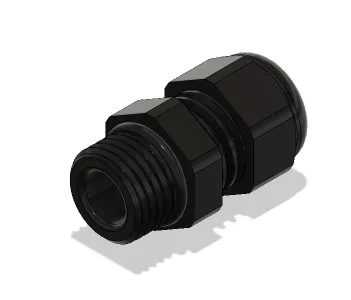
I couldn't find my stash of reducing spacers anywhere and a search of thingiverse turned up nothing.
When I turned to modeling spacers I thought it would be much more secure to make a spacer that the PG7 would screw directly into. I also wanted to use a solid screwed connection that filled the 3/4 hole for better security. I thought what I really need is a PG7 and PG13.5 combination piece.
But Fusion lacks the thread presets for DIN PG connector threads and I didn't want to go thru the effort to add them. So how to quickly model this combo piece?
Use the parts bodies and cutting tools that are readily available from mcmaster carr. Here is how I made this part:
I created a new component called adapter.
I selected insert mcmaster carr component and searched PG13.5 wire gland. I downloaded the step file and hit ok to insert into the fusion file.
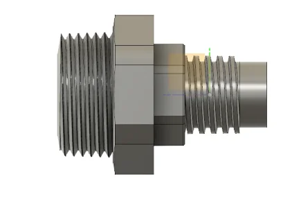
Next I went to the component bodies and hid all the bodies except the main core of the PG13.5 as below.
Next I created an offset plane along the line I wanted to sever this part in two. Then selected modify "split body" selected the core and then the construction plane as the splitting tool. This is the result (after I selected the cast off portion of the body and hit "remove"
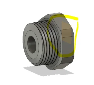
So now I had the portion that goes into the 3/4" hole in the electrical cabinet. But I needed to add threads to screw the PG7 into. How to get those when the thread tool doesn't have the correct threads? Cheat some more.
I went back to insert and downloaded the PG7 part from mcmaster carr.
I selected the PG7 bodies and hid every body except the core body again. I then moved the PG7 core into the unthreaded hole in PG13.5 like this:
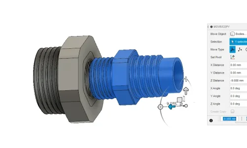
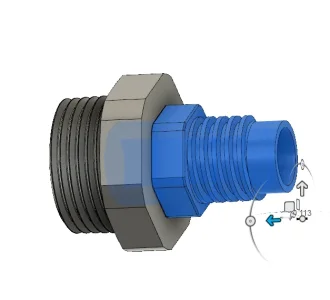
Then with PG7 body still selected I hit modify and then scale and entered 1.01 for the scale factor just to create a little more thread clearance when the next step is performed.
Then I selected the PG13.5 body and selected modify and split body. I then selected PG7 as the splitting tool. This cuts the internal threads out of the PG13.5 core.
This leaves the part complete as I want it printed.
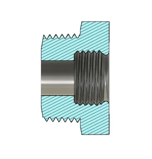
Export to cura as per normal and print.
The result:
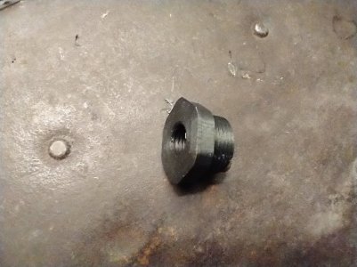
It took way longer to write this than model the part. it took me literally less than 4 minutes to model this part to match the pg7 wire gland I have and the pg13.5 retaining nut I already have... but I'll model new nuts anyway.
In Mcmaster's models many of these types of parts dont have the thread cut in them so you would just use the same above technique

