• Scam Alert. Members are reminded to NOT send money to buy anything. Don't buy things remote and have it shipped - go get it yourself, pay in person, and take your equipment with you. Scammers have burned people on this forum. Urgency, secrecy, excuses, selling for friend, newish members, FUD, are RED FLAGS. A video conference call is not adequate assurance. Face to face interactions are required. Please report suspicions to the forum admins. Stay Safe - anyone can get scammed.
  • The 2026 Calgary Area Meetup is set for Saturday May 30th at 10am. The signup thread is here! Robinhood has graciously offered to host the meetup again this year. Please note that you MUST RSVP to the notice linked above if you wish to come.

Building SSQA for tractor loader from scratch

I still really like a jib boom on small loaders. If you're loading stuff in and out of pickups, way less chance of damaging anything. It's less versatile than a Hiab, but same idea. Plus more visibility than trying to see around a bucket. Makes moving truck cabs, boxes, engines, anything really, so much nicer if you're working by yourself
 
Makes moving truck cabs, boxes, engines, anything really, so much nicer if you're working by yourself

I'm partial to the ones you use with Forks, but something that hooked to my loader arms directly would be ok too. My loader bucket is about 7ft in front of the tractor so a boom isn't essential.

The ones that go on a 3pt hitch are cheaper and more common but won't lift nearly as high. I have one that I rarely use. A chain on the side lip of my front bucket is almost always faster and often better.
 
I'm partial to the ones you use with Forks, but something that hooked to my loader arms directly would be ok too. My loader bucket is about 7ft in front of the tractor so a boom isn't essential.

The ones that go on a 3pt hitch are cheaper and more common but won't lift nearly as high.
A lot of yards use backhoes, take the front bucket off and replace it with a jib boom. The back bucket and stick is gone, instead they STACK the weights on there. But that's all they are for, lifting or dragging
 
A jib boom is planned for the future. I agree with their merits and can see one being super handy. I want as many different ways to lift thing that I can get 🙂. Work spoils me with proper equipment, then I come home and have to work in the stone age. Even the Egyptians have more advance lifting devices than i currently do.
 
I'm partial to the ones you use with Forks, but something that hooked to my loader arms directly would be ok too. My loader bucket is about 7ft in front of the tractor so a boom isn't essential.

The ones that go on a 3pt hitch are cheaper and more common but won't lift nearly as high. I have one that I rarely use. A chain on the side lip of my front bucket is almost always faster and often better.
You need a set of over bucket forks.
 
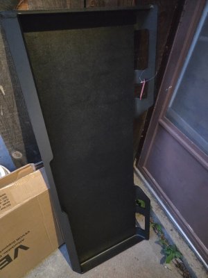
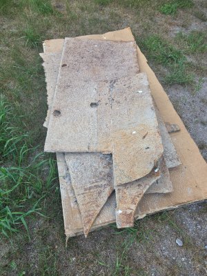
Vevor plate arrived. Its heavy.... i only unboxed it, didn't measure anything, ill get to that tomorrow. Came with a couple nice big square blocks of Styrofoam im saving for casting too🙂.
20260623_212139.jpg
 
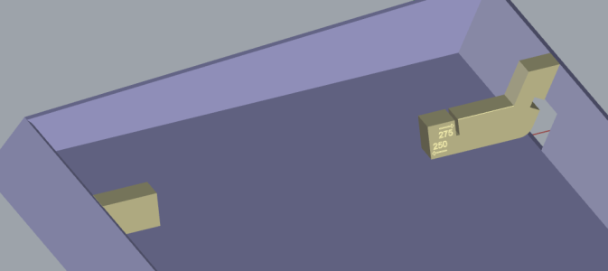
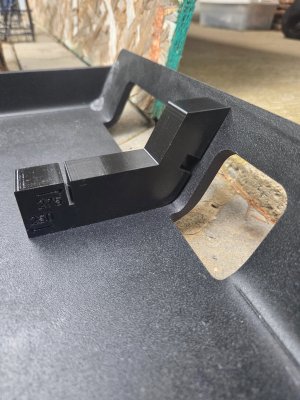
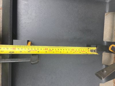
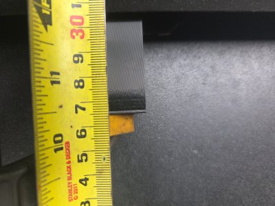
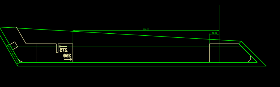
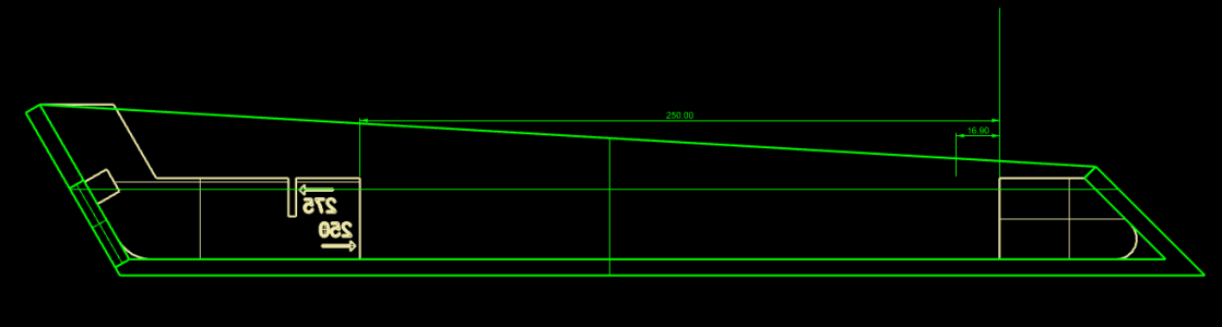
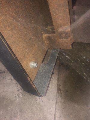
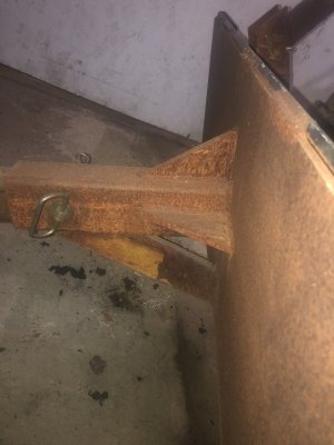
Modeled these simple measuring blocks to help measure exactly what the vevor plate is and will send them to print once my drying cycle is done in about . These are drawn from the ISO standard with a nominal 250mm gap shown, so I can gauge what the vevor plate is actually built to. the rest are straight forward tape measurements.

1782488743260.png

20260626_131752.jpg
20260626_131747.jpg
20260626_131830.jpg
20260626_131823.jpg

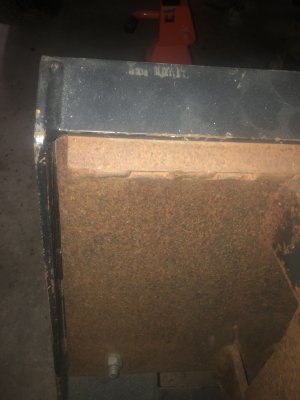
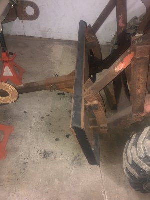
now I can start drawing it up and seeing how close it is. I can already tell the latch holes are bigger, and it's also 1140mm wide, vs the 1131 in the std.
 
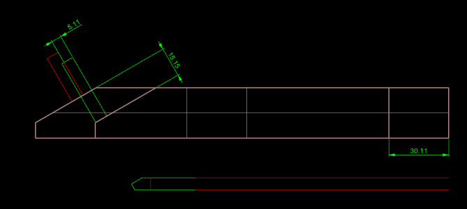
After modeling it, there are a few differences aside from the width. the 60* bottom face is 5mm bigger, and the latch pin hole edges are 15mm farther out.
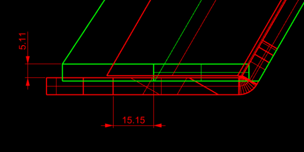
1782500464545.png

the 5mm face I think will be fine if I build to the std, but for the 15mm difference in latch pin holes, I think I'll build to the std, and modify the plate by welding in a pice to make the gap. As for the width, I'll build to the std also, and might include provisions to add bolts or plates to take up the slack in the side to side play. Either plates on individual implements, or maybe bolts on the sides of the qa plates on the tractor themselves.

The biggest head scratcher though is the location of the latch holes side to side....
1782500763599.png
1782501059684.png

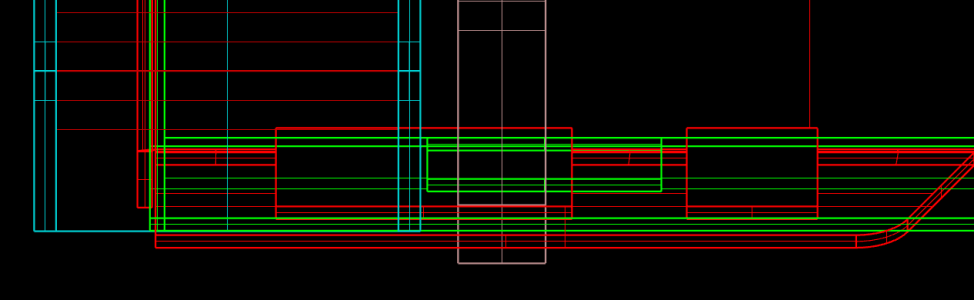
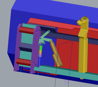
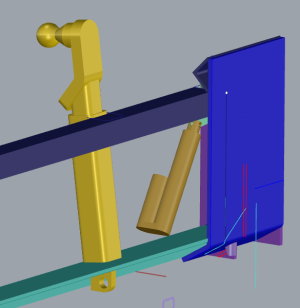
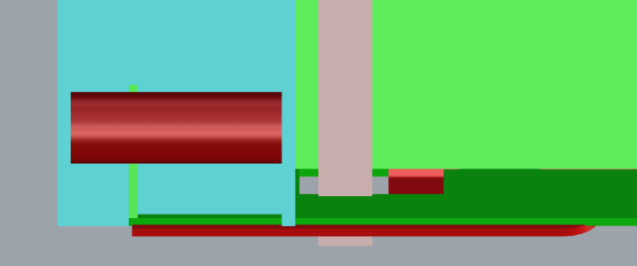
If I position them off center on the std holes, i'll catch these holes in the plate, and still catch holes in plates made to the std. All while avoiding the space needed for the tractor mount. I think it'll be fine though considering I will most likely be making every attachement myself, and can modify whatever else comes my way to fit it. But getting those pins right side to side isn't something that can be easily changed, so I want to nail that down.

Green is ISO Std plate
red is vevor plate
blue is loader arm bracket
brown is latching pin

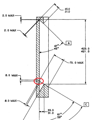
My big concern was the proper fit between the two angled datum surfaces, and making sure I'm in the ballpark there as that fit is critical to the entire thing. I will make my tractor side to the ISO std, as it's the LMC. My 3d printed measuring blocks really helped out translating the actual dimensions to cad, I like using stuff like that to measure difficult shapes. Even though I made a mistake when I initially drew my ISO Std plate in cad......and didn't catch it until I was wondering why the vevor plate was WAAAAY off......I read the drawing wrong, and didn't catch it until then.....I made the 421 dimension to the inside angle intersection circled in red....Rookie mistake....😉 That makes the #'s on the side of my 3d printed blocks null and void, but I'm not going to bother printing new ones.....or am i?
1782501365277.png
 
1782501715619.png

Just a quick and dirty, but wil only 30mm travel different in the latch pins I can accommodate both. I think that's manageable within the over center latch linkage, so I'll go that route.

I would really like to know why it's different, and if it's built to another standard or something. I feel like I'm missing something....
 
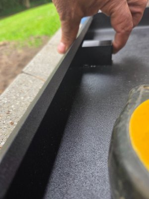
IMG_5906.jpegIMG_5907.jpegIMG_5908.jpegIMG_5909.jpegI don't really think I'm helping here, at all.

You probably want a bit of "slop" to mate attachments. You will "probably" not have clean or straight alignment points.

I never did figure out a bottom pin, the bolts work, for me, it works.

But that is a legit home brew SSQA plate, bracket and all, besides the locking pins it's designed to use other implements
 
I agree. I'm building in 5" of side to side play, and the 5mm gap at the bottom will be fine and wanted. That surface isn't a datum surface so clearance is clearance.
I would actually help with measurements and stuff, if wanted, mines more redneckery built

I think I was more encouraging that I've built one, you can too

If that makes sense 🙄

Mine was basically built from scrap minus the SSQA frame, which follows your preferred method of home brew
 
View attachment 83620View attachment 83621View attachment 83622View attachment 83623I don't really think I'm helping here, at all.

You probably want a bit of "slop" to mate attachments. You will "probably" not have clean or straight alignment points.

I never did figure out a bottom pin, the bolts work, for me, it works.

But that is a legit home brew SSQA plate, bracket and all, besides the locking pins it's designed to use other implements
I was going to comment yesterday basically the same as Chicken is saying, with the horsepower and lifting force your outfit will produce doesnt need "full contact engagement" the same as a more robust industrial machine needs. A 4-spot engagement of 1/2" x 3" flat iron ( a short 4" section in each corner welded to a framework of angle will be absolutely enough for your machine).
Chicken used a bolt for securing the implement from accidental removal and it will surely give secure attachment but I think I would go with a sliding pin affair myownself just for simplicity of different implement hook-ups the same as the "big boys" do....only thing is I would give my pin pockets & pins lots of "slack" for ease of insertion ( I might even taper the pins a slight bit)...again, your HP-machine size require an absolute no-slack implement after hook-up the way a 4 yard front end loader with 10,000 lb lift capacity would require.
 
I've gone around in circles, digging through my scrap piles, and stock racks. I've designed this thing a few different ways, using all types of material, but i think this is probably the best way to go. Not sold on the crossmembers though, I'll probably change them to 2"x 1/4" wall hss, or something different as I go, but for now I'm mostly concerned with just nailing down the plate design so I can get going on it. Also the locking pin/overcenter dimensions that work with stuff I have in stock.

1783130900757.png
1783131104538.png

Currently have everything I need to proceed, except the linear actuators, but it'll still work manually. We'll see how tomorrow goes but if it's as hot as today was in the shop, I probably wont get far....

I found some 3/8" plate I salvaged from work that I'll use for the big flat plates. They were in the box of the truck and I forgot about them 😀. That was the reason for all the other designs because I didn't have enough plate to make it this way and didn't want to buy anything. The rest I have flat bar for. Debating using the brackets that are on the bucket right now and cutting them up to fit, vs making from scratch. I'll probably just use the current ones and save some time.
20260702_142153.jpg
 
What's the end goal for lifting? If I missed it my apologies. Mines around 800 pounds, but I do have a shorter jib to up that limit. My biggest downfall is not enough ballast at the back end
The loader will do 2500 according to the internet. I'm going to add some lifting lugs for shackles near the attachment points of the loader arms so that with no attachments I'll still be able to sling stuff to max capacity, and have a better view of it hopefully without the bucket. Along with some grab hooks here and there for chains too. I want to be able to lift stuff using the ssqa adaptor plate itself with no attachment on. I'm hoping to be able to lift a 20' 24" dia log (sawmill max capacity) onto the bunks of the sawmill with just my log hooks hanging off the frame. A white pine log that size is about 2700, ash is 3000, so that might be pushing it. Might have to push them up ramps..... For the eventual jib, I have no weight goals other than being able to stand up timber frame bents, or standing up trusses. That's about the only use I can see atm that would stretch it. The tractor is stout enough that I'd likely break something or crap myself before It got light in the ass end 🙂.

I'm hoping to keep the added weight with the bucket attachment under 50-60lbs, but I haven't done any math on that yet, just trying to pare it down to the bare necessities as I go, and keep it as tight to the pins as I can. Right now I've only added an extra 0.5" in distance from the back of the bucket to the pins compared to stock. I could probably knock it back to zero if I clearance the ssqa side plates on every attachment though. But i'll probably actually increase it to 0.75" just for more wiggle room. I wish the ssqa plates were about 10" wider, it would fit this loader a lot better. I really thought about making it wider and just going with my own "standard", as I'm most likely be making everything else too, but want to keep it open for purchased stuff. I'll probably just buy the fork attachment as I don't have enough material to build one here, and I can get 60" forks and the frame for $750 done ready to go. I need to pick and choose my battles, and I think that one better fought with the wallet. I've already built my 3 point fork attachment so I got that merit badge.....
 
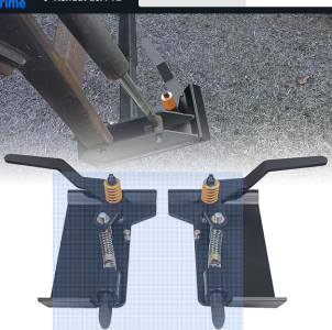
Well this is turning into more of a Betty Crocker cake than a scratch build.....I just caved and ordered these

1783188892235.png

I'll still have to crack a few eggs to make the pin on tractor side, but I decided buying the time was the better path to take for this one.....Too many other things going on right now.

At least I got the shop cleaned up this afternoon though lol. the final straw was getting everything setup to plasma out those plates in the backyard and getting chased inside by the rain for the 3rd time. That's when I sat down to print out the detail views for the pins so I could start machining those instead but the more I got thinking about it, even if I used just the pins above I'm still ahead with all the machining I'm saving.
 
Back
Top